22 June 2012
FORWRD FUSELAGE

Two pieces of L-Angles trimmed 40mm long. The center line on one flange is marked and layout two rivet locations 10mm from each end.

Then, for the left fuselage L-Angle , clamped.

First mark is drilled with #40 drill bit.

Then, second mark is drilled with #40 drill bit. As seen in the picture, third mark is also drilled. This mark is for the Left Side Cabin.
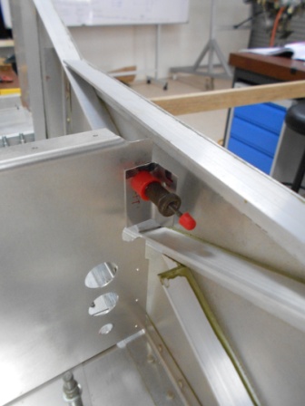
Then, the L-Angle is then fitted into the left side cabin to see for any interference.

Then, the L-Angle is then taken out from the left side cabin and fourth mark is then drilled with #40 drill bit. The edge of the L-angle is trimmed for the side fuselage assembly clearance.

The L-angle is then fitted with the left cabin side and fastened by #40 grip pin.
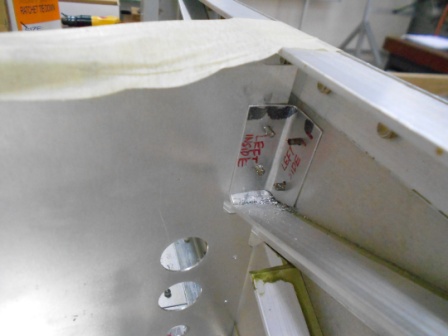
The L-angle is then drilled #40 drill bit through the left side of the L-angle and left cabin side

For the right side cabin fuselage, the L-angle is clamped with a G-clamp.

First mark is drilled with #40 drill bit.
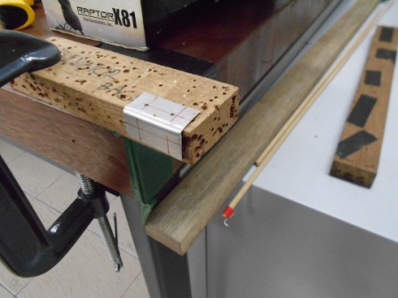
Then, second mark is drilled with #40 drill bit.
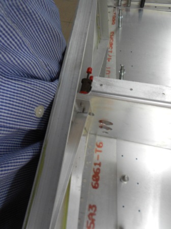
The L-angle is then fitted and clecoed to the right side cabin to check for any interference with the structure.
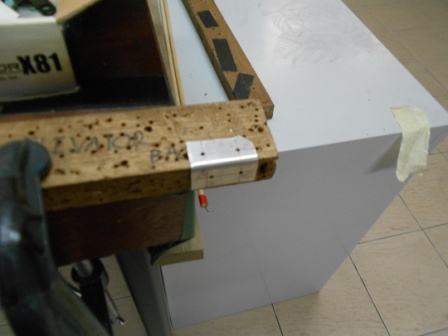
Then, the bottom edge of the edge L-angle is trimmed to fit with the right side cabin fuselage. The tolerance between the mark and the trimmed edge satisfy the construction standard. The other two mark are then drilled with #40 drill bit.

The L-angle is then clecoed to the seat front with two grip pin. With seat base attached (75F11-4), we sure that the L-angle is in the correct position. Then, we drilled through the L-angle and right side cabin fuselage with #40 drill bit.
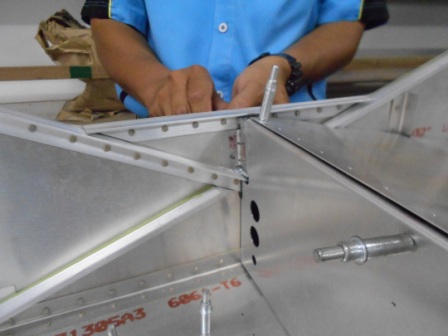
We drilled through the L-angle and the right side cabin fuselage for the second mark as we have clecoed the previous hole that we have drilled before. We also use #40 drill bit.

We enlarge the #40 holes through the L-angle and left side cabin fuselage with #30 drill bit by using grip pin.

Pictures shows both holes has been enlarged into #30 hole size for the L-angle and left side cabin.
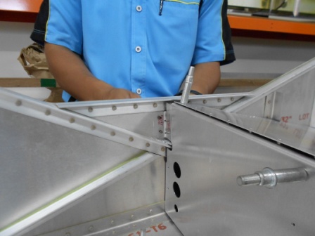
With the right L-angle is clecoed, we enlarged the hole through the right side cabin fuselage with #30 drill bit.

Pictures shows both holes has been enlarged to #30 hole size and grip with #30 size grip pin (yellow pin).
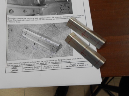
Two pieces of 90mm long L-angle is cutted as shown in the picture. The center line is marked on one flange and 10mm rivet location are marked from each end and one in the center.
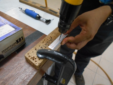
With a #40 drill bit, we have pre-drilled the center mark for the left side cabin.

The pictures show #40 hole size at the center of L-angle on one of the flange.

The L-angle for the left side cabin is then fitted to the seat front and gripped with red grip pin. The center line on the flange is adjusted so that it is visible through the pilot holes at the seat front.
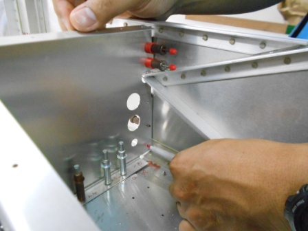
The center line is then marked by pen through the two holes on the seat front.
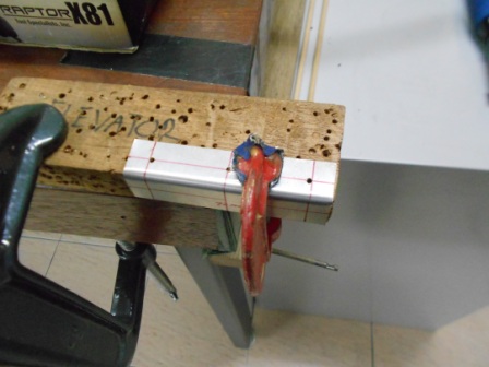
Both marks are then drilled with #40 drill bit as shown in the picture.
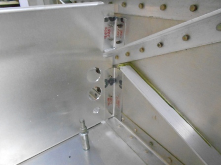

The L-angle is then fitted to the seat front and gripped with #40 grip pin. Three #40 holes also has been drilled on the flange.
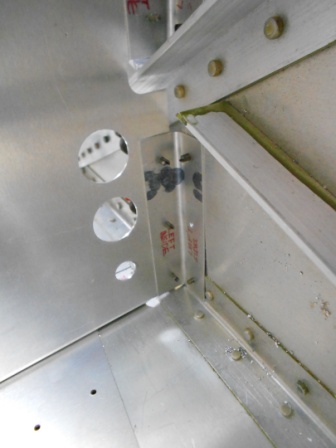
The L-angle is then drilled through the left cabin side fuselage and clecoed with #40 drill bit on the three marks.

For the right side L-angle on this section, we have done steps as previous left side L-angle. The L-angle is pre-drilled with #40 on the right inside flange at the center and then at both ends.


The right side cabin L-angled is then fitted to the seat front and grip with #40 grip pin. Then, the L-angle is the back drill through the cabin side with #40 and gripped with #40 grip pin. 3 holes drilled for this action.

The left side cabin fuselage #40 holes is then enlarged to #30 size through the 90mm L-angle.
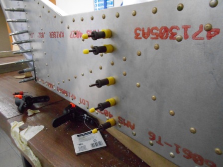
The picture shows the holes (Bottom three) has been enlarged to #30 hole size and grip with #30 (yellow) grip pin.
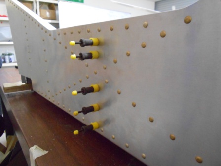
Then, for the right side cabin, we have also enlarged the holes (Bottom three) and grip pin with #30 grip pin through the right side cabin and the L-angle.
