
16 May 2012
FUSELAGE ASSEMBLY

The left and right forward fuselage was drilled with a #20 drill bit. From the construction plan,
75F4-1 (side channel MWO) left and right fuselage was allocated.
The left side channel (75F4-1) was secured with a #40 clecoes and the holes to be drilled
was set between the top hole of the side channel until the third upper hole
from the forward fuselage left longeron happen.

The left side channel (75F4-1) was drilled with a #20 drill bit, staggered with #40 clecoes
gripping the left fuselage and the left side channel. The #40 clecoes were disattached,
abd the remaining hyoles were drilled with a 20 drill bit until the third upper hole
of the side channel from the forward fuselage left longeron opening.

The right side channel (75F4-1) was drilled with a #20 drill bit through the skin, staggered with #40 drill clecoes
that grip the right side channel and the right side fuse;age. Then the #40 clecoes were disattached
and the remaining holes that are not drilled yet with #20 drill bit were drilled.
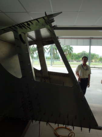
The drilled holes #20 were shown in the picture.
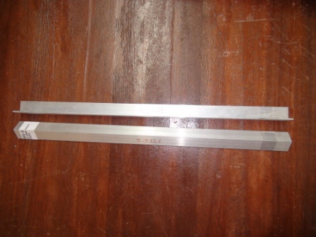
The side channel extrusion (75F6-6) was labeled with sharpie pen.

From the video construction, both side channel extrusion was marked with a centerline along the part.
Then 10mm distances from each edges were marked.
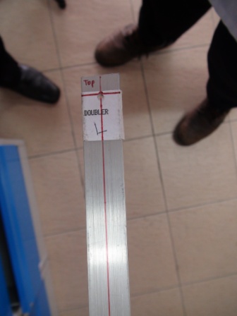
Then, the 10mm distances mark was drilled with a #40 drill bit on one side of the right side channel.

The right side channel extrusion was grip with grip pin on the right side channel MWO.
After the line was lined up with the holes on the side channel MWO, the side channel extrusion was clamped.
With a #40 drill bit, the pilot holes on the right side channel were drilled through the right side channel extrusion.

With a #20 drill bit, the holes were then enlarged to #20 size staggered with #40 grip pin.
The other remaining pilot holes were enlarged to #20 size holes through
the right side channel and right side channel extrusion.

Left side channel extrusion was drilled on the 10mm mark from the edge.

The left side channel extrusion was gripped by grip pin size #40, then with a #40 drill bit,
the left side channel MWO was drilled through the left side channel extrusion.

With a #20 drill bit, the left side channel MWO was drilled through the left side channel extrusion.

Both side channel and d=side channel extrusion were drilled with a #20 drill bit.