
9 January 2014
LANDING GEAR SECTION
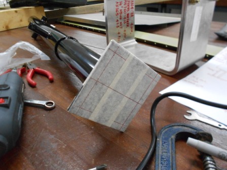
Today, we continue with the landing gear. A center line is marked on the top of the Doubler
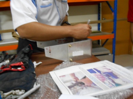
A 5mm line from the front and back edge of the Doubler is then marked to position the Nose Gear leg on the fork and doubler
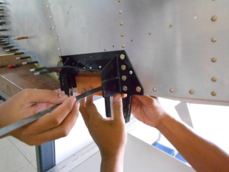
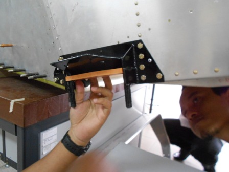
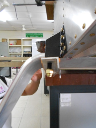
The Bottom Bearing is then positioned around the Nose Gear leg. The Nose Gear leg is then slide into the Upper Bearing and the Bottom Bearing is then pushed between the flanges of the Center Firewall Stiffener until the Bottom Bearing is against the back of the Center Firewall Stiffener
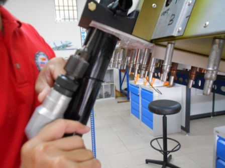
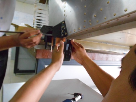
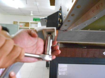
Next, we back drill through the Lower Bearing Support into the Bottom Bearing with a #40 drill bit. This process will be continue on the next day to expand the holes to #30 and # 3 drill bit with Table Drill
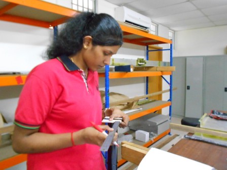
Then, we layout 3 bolts locations on each side of the Nose gear leg plate
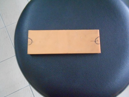
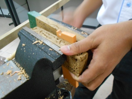
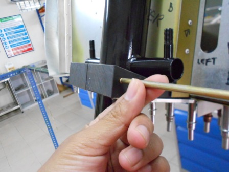
The Rubber Support (75L2-2) is then notch to clear the Studs on the Gear Strut Fittings. The notches is centered on the bottom support rubber. The Top Support Rubber notches is offset to one side
The Top Support Rubber on the Gear Strut Fittings installed between the Studs
Then the Gear is then slide into place between the studs. The Bottom Support Rubber and the Main Gear Support installed into place
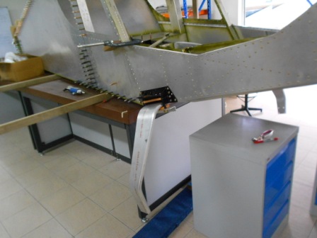
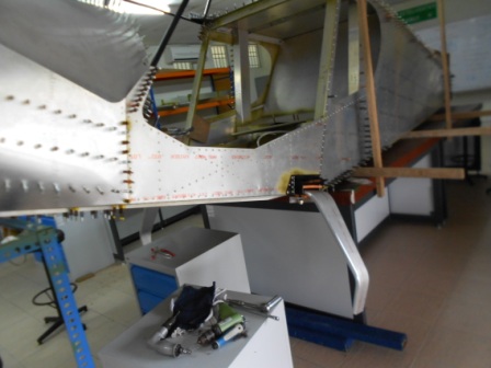
Our milestone until to this date