
14 January 2013
RUDDER CONTROL
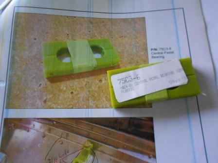
This is the Central Pedal Bearing (75C3-6).
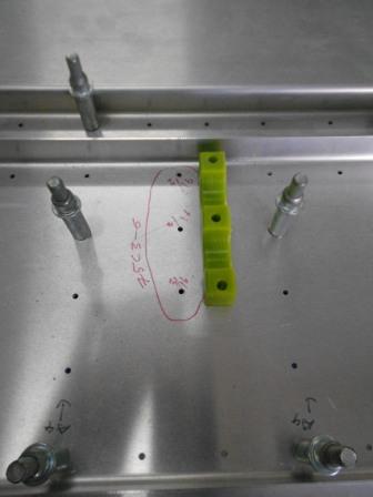
We then locate the position of the Central Pedal Bearing and identify the three holes that need to be drill with #12 drill bit.
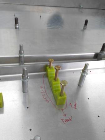
After the holes has been enlarged with #12, the lower half of the Central Pedal Bearing is then set in place on the Bearing Channel with AN#-6 Bolt.
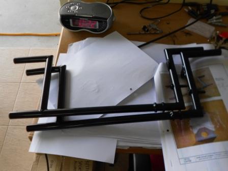
This is the Rudder Pedal (75C3-4), that we have undercoat to protect the steel from corrosion.
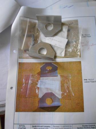
And this is the Lateral Pedal Bearing (75C3-7)
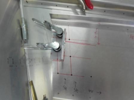
We then slide the Lateral Pedal Bearing on the end of the Rudder Pedal. We have set the Pedal on the Central Bearing. We have checked with drawing 75-CA-3 for proper orientation. The distance is measured from the flange of the Bearing Channel to the center of the Pedal at the Central Bearing. On the Passenger Side, it is measured 49 mm. We then set the outboard end of the Pedal the same distance. The Lateral Bearing is then positioned so there is sufficient edge distance for the rivets.
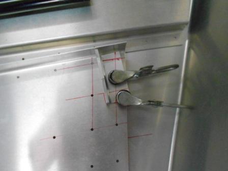
We then slide the Lateral Pedal Bearing on the end of the Rudder Pedal. We have set the Pedal on the Central Bearing. We have checked with drawing 75-CA-3 for proper orientation. The distance is measured from the flange of the Bearing Channel to the center of the Pedal at the Central Bearing. On the Pilot Side, it is measured 15.9 mm. We then set the outboard end of the Pedal the same distance. The Lateral Bearing is then positioned so there is sufficient edge distance for the rivets.