
15 January 2013
RUDDER CONTROL
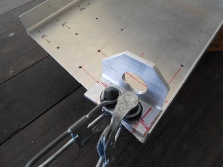
As in previous operation, we have positioned both Lateral Side Bearings (75C3-7) with the same distances from the flange of the bearing channel to the center of the Pedal at the Central Bearing. We have then finalized the position of the Pilot Side Lateral Side Bearing so there is sufficient edge distance for the rivets. We also have set the lateral Side Bearing so that it satisfied the edge distance, 7 mm. The lateral Side Bearing is also positioned so that it is perpendicular to the Bearing Channel for the Pedal placement. The Lateral Side Bearing is the clamped in position with clamps.
Then, we have then finalized the position of the Passenger Side Lateral Side Bearing so there is sufficient edge distance for the rivets. We also have set the lateral Side Bearing so that it satisfied the edge distance, 7 mm. The lateral Side Bearing is also positioned so that it is perpendicular to the Bearing Channel for the Pedal placement. The Lateral Side Bearing is the clamped in position with clamps.
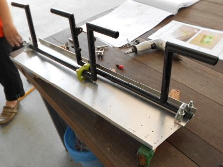
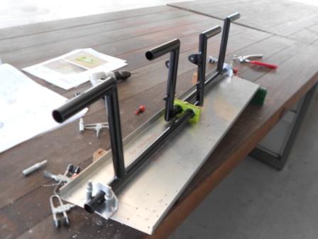
Above is a picture that shows both Lateral Side Bearings (75C3-7) are positioned on both side of the Bearing Channel. The Bearing Channel is placed on top of two woods to support the assembly.
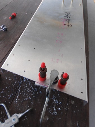
Now we move on to the lateral Side Bearing on the Passenger Side. With a #40 drill bit, we then drill through the Bearing Channel to the Lateral Side Bearing. The hole is then gripped with #40 grip pin (in red), and clamped together to hold the position of the Lateral Side Bearing. Then, the other hole is the drilled through the Bearing Channel to the Lateral Side Bearing with #40 drill bit. Then, the holes are gripped with #40 grip pin (red). The positioned of the Lateral Side Bearing is then checked for its consistency of the perpendicularity and the distance from the Bearing Channel and all are satisfying.
Now we move on to the lateral Side Bearing on the Pilot Side. With a #40 drill bit, we then drill through the Bearing Channel to the Lateral Side Bearing. The hole is then gripped with #40 grip pin (in red), and clamped together to hold the position of the Lateral Side Bearing. Then, the other hole is the drilled through the Bearing Channel to the Lateral Side Bearing with #40 drill bit. Then, the holes are gripped with #40 grip pin (red). The positioned of the Lateral Side Bearing is then checked for its consistency of the perpendicularity and the distance from the Bearing Channel and all are satisfying.
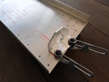
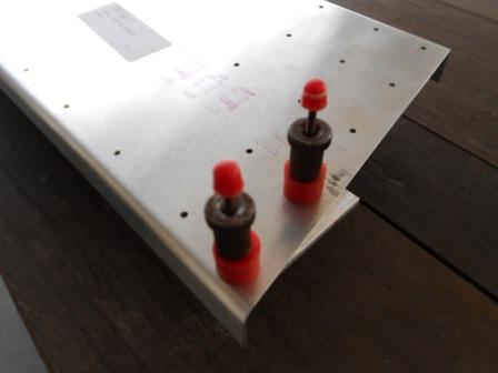
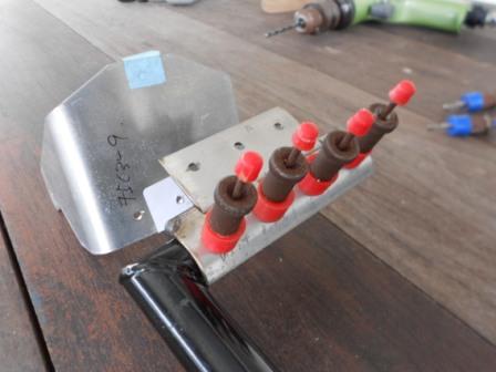
The grip pin is then replaced with #40 clecos in silver colour. The Rudder Pedal (75C3-4) is then inserted to the Lateral Side Bearing and Central Pedal Bearing. We then inserted the other half of the Central Pedal Bearing and pushed in the AN3-16 bolts. We then tested the Rudder Pedal and the movement is satisfying. No hard friction feeling on the Rudder Pedal when we move the Pedal with hand. The movement is smooth.
This is another picture of the assembly of the Rudder Pedal, Lateral Pedal Bearing, Bearing Channel and Central Pedal Bearing.
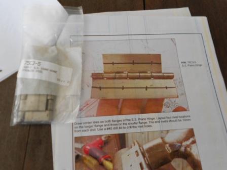
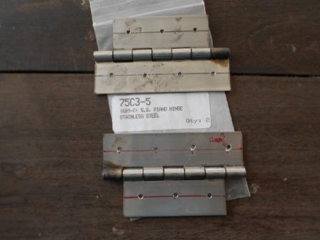
Now we move on to another part that is S.S. Piano Hinge (75C3-5). The parts are then identified and match the part number in the photo guide. The S.S. Piano hinge that in our inventory is quit oily, maybe for the corrosion protection, so we decided to clean it up with a thinner and a rug. It is hard to make a marking on the part if the surface is not clean up.
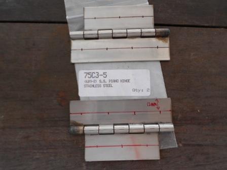
So this is the S.S. Piano Hinge as we have cleaned it up. We have checked the S.S. Piano Hinge and the part is in good condition and no problem found. A center line is drawn on both flanges of the S.S. Piano Hinges. Four rivet locations on the longer flange and three on the shorter flange are then layout. The end of the rivets is measured to be 10mm from each end. The other rivets on the center is measured equally spaced.
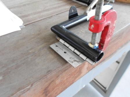
As in this process, we have clamped the S.S. Piano Hinge on a wood with a g- clamp. And drill out those rivets holes with #40 drill bit.
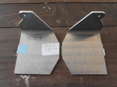
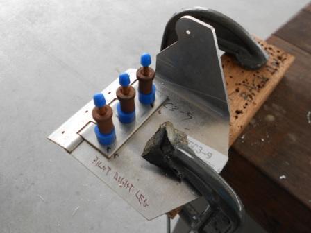
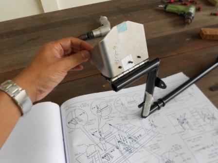
This is the Toe Brake Pedal (75C3-9) in our inventory. The parts are checked for consistency and no problem with the parts. The Part Number is also the same with the photo assembly guide and the drawings.
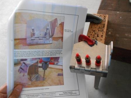
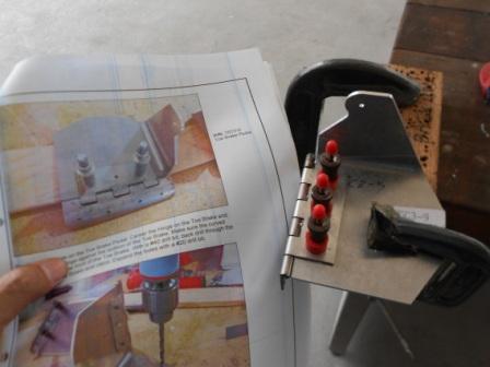
We then positioned the Hinge on the Pilot Left Leg, Toe Brake Pedal. The hinge is then centered on the Toe Bake and the Barrel of the Hinge against the bottom of the Toe Brake. The curved flange is then checked that it is towards the front of the Toe Brake. The assembly is then griped with G-clamp. With a #40 drill bit, we then back drilled through the Hinge into the Toe Brake and griped with three #40 grip pin. The Assembly is then checked for consistency of the assembly with the drawings and the photo guide and no issue about this.
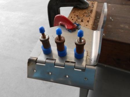
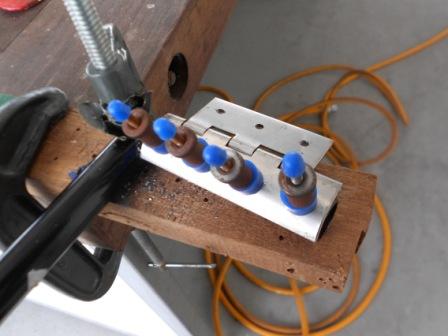
The #40 holes that are drilled before are then enlarged into #20 size through the Hinge and Toe Brake Pedal. The holes are then griped with #20 grip pin as shown in blue color.
We then positioned the Hinge on the Pilot Right Leg, Toe Brake Pedal. The hinge is then centered on the Toe Bake and the Barrel of the Hinge against the bottom of the Toe Brake. The curved flange is then checked that it is towards the front of the Toe Brake. With a #40 drill bit, we then back drilled through the Hinge into the Toe Brake and griped with three #40 grip pin. The Assembly is then checked for consistency of the assembly with the drawings and the photo guide and no issue about this.
The #40 holes that are drilled before are then enlarged into #20 size through the Hinge and Toe Brake Pedal. The holes are then griped with #20 grip pin as shown in blue color.
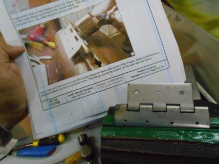
With a vise and hammer, we then curved the longer flange of the Pilot Right Leg S.S. Hinge to match the curve of the Pedals. We have followed the photo guides to make small bends in several locations to form a smooth curve. The flange is curved on the side with the barrel.
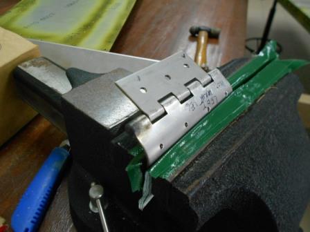
With a vise and hammer, we then curved the longer flange of the Pilot Left Leg S.S. Hinge, to match the curve of the Pedals. We have followed the photo guides to make small bends in several locations to form a smooth curve. The flange is curved on the side with the barrel.
We then continue the process of this assembly by set the Hinge on the Rudder Pedal. We have checked that the end of the long flange is flushed with the end of the Pedal. The Hinge Barrel is also positioned so that it is laying on the Rudder Pedal with the Longer Hinge is vertically positioned with the Rudder Pedal as in the Drawing, 75CA-3.
As shown in this picture, it is explained that the Hinge Barrel is positioned so that it is laying on the Rudder Pedal with the Longer Hinge is vertically positioned with the Rudder Pedal as in the Drawing, 75CA-3.
The Rudder Pedal is then clamped with G- Clamp and with a #40 drill bit, we then back drill through the Hinge into the Pedal and grip with #40 Grip Pin, red color.
Then, with a #20 drill bit, we enlarged the #40 holes as shown in the picture. As in the picture, it is shown that one of the holes is slightly off, and not aligned with the other three holes, but I decided that this is still acceptable as the hinge and the Rudder Pedal is in circular.
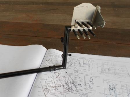
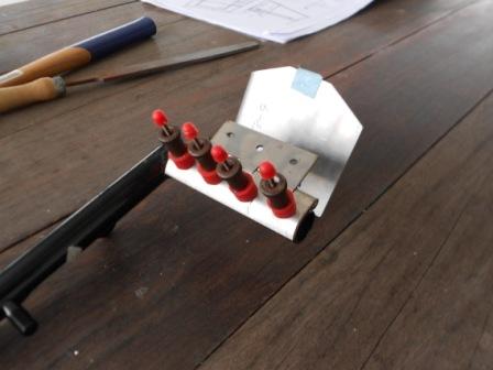
As in this picture, it is shown that the assembly is clecoed with #20 Cleco and finished this operation on one of the Rudder Pedal.