
30 January 2013
RUDDER CONTROL
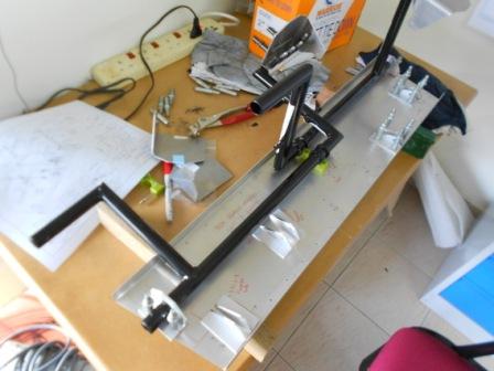
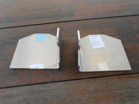
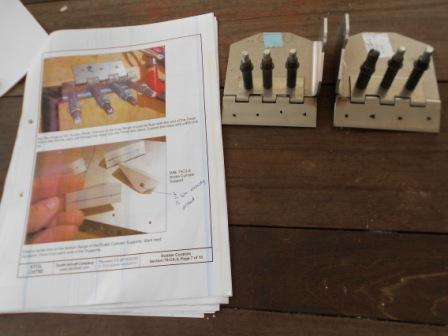
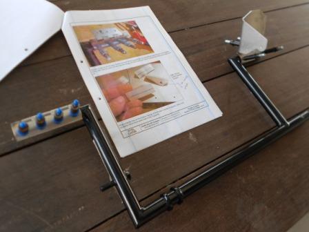
As for today, we will continue on the process of assembling the Dual Brakes for our aircraft. The reference drawing is 75-DB-1. As shown in the picture, we have arranged 2 pairs of the Brake Cylinder Supports (75C3-8) on the Pedal Bearing Channel.
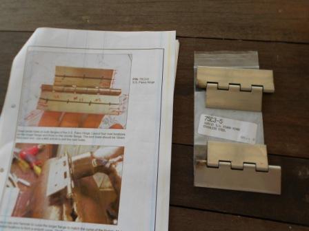
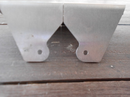
As in the picture, we have check the S.S. Piano Hinge (75C3-5) and clean it up with a thinner.
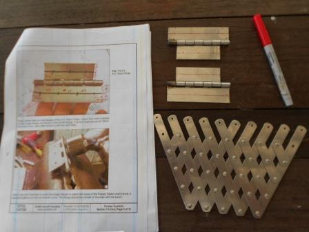
We then draw the center line on both flanges of the S.S. Piano Hinges. Then, four rivet locations are then layout on the longer flange and three on the shorter flange. The end rivets is positioned to be 10mm from each end.
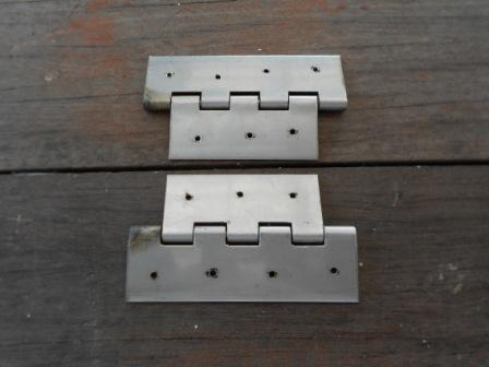
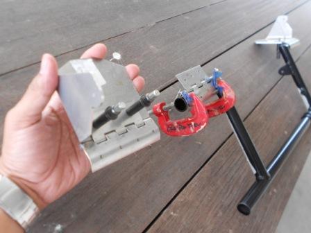
By clamping it with a G- clamp, with a #40 drill bit, we then drill the rivet holes. On our drilling, we have miss drilled the position and somehow offset a few millimeter from the center line towards the barrel.
Picture above is the Toe Brake Pedal (75C3-9) for the passenger side.
We then positioned the Hinge on Toe Brake Pedal. Centered the Hinge on the Toe Brake and the barrel of the Hinge against the bottom of the Toe Brake. We then make sure that the curved flange is towards the front of the Toe Brake. With a #40 drill bit, we then back drill through the hinge into the Toe Brake and cleco. With a #20 drill bit, we then expanded the holes.
With a bending machine, we have bended both the longer flange to match the curve of the pedals. We have made small bends in several locations to form a smooth curve. The flange is checked to be curved on the side with the barrel.
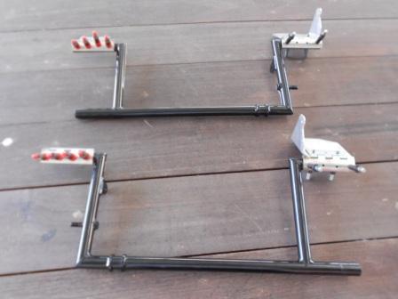
We then set the Hinge on the Rudder Pedal. The end of the long flange is checked to be flushed with the end of the Pedal. With two persons, the Rudder Pedal is the hold by one person, and the other person back drill through the Hinge into the Pedal with a #40 drill bit and cleco. Both of the Rudder Pedal are shown as in picture above.
With a #20 drill bit, we enlarged the holes same as in previous operation. With#20 grip pin, we then cleco the Hinge Pin to the Rudder Pedal. Above is the Rudder Pedal for the Pilot and Passenger Left Foot.
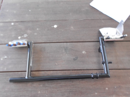
Then, with a #20 drill bit, we enlarged the holes same as in previous operation. With#20 grip pin, we then cleco the Hinge Pin to the Rudder Pedal. Above is the Rudder Pedal for the Pilot and Passenger Right Foot.
In the mean time, we have use a #12 drill bit to expand the hole for the Brake Cylinder.
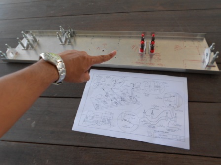
Then, we positioned the Supports on the Pedal Bearing Channel for the Passenger Left Foot. With the lines visible through the predrilled holes back drill through the Pedal bearing Channel into the Supports with a #40 drill bit and clecoed with grip pin. Then the other support is positioned so that it is 13 mm away from the first supports and aligned with the first supports. A line is drawn parallel to the Rudder pedal Channel and a bolt is inserted through both of the supports to make sure that both are aligned. Then with a G-clamp, we clamped the supports and with a #40 drill bit, we then drill through the Pedal Bearing Channel and the Supports. The dimensions are checked so that it is under the tolerance for an A5 hole.
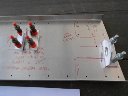
In this picture it is shown that we need to continue the work for the other supports that is for the Slave Cylinder for the Passenger Right Foot.