
31 January 2013
RUDDER CONTROL
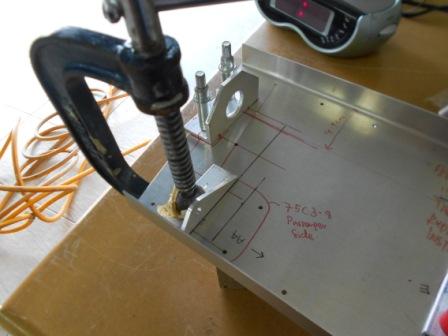
As for today, we started to continue the assembly for the Supports on the Pedal Bearing Channel for the Passenger Right Foot. We have drawn a line that is referred to the cabin floor, 18mm (the black line laying on the supports). Then we continue to make a line that is 13 mm away from the first black line such as stated in the 75-DB-1. The support is then trimmed with a file for 1 mm to match the bend on the Pedal Bearing Channel and also so that it will satisfy the distance from edge for the supports. The support is then clamped with a G-clamp and two points are marked and measured so that it will satisfy the edge distance. Everything is fine.
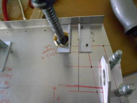
The first support is then drilled through the Pedal Bearing Channel with #40 drill bit. Then, same as previous operation we then positioned the second support for Passenger Right Foot and clamped it with G- clamp. The support is then checked so that it is right, 13 mm away from the first support as in the plan.
With a #40 drill bit, we then drilled through the Pedal Bearing Channel to the second support and clecoed with #40 cleco.
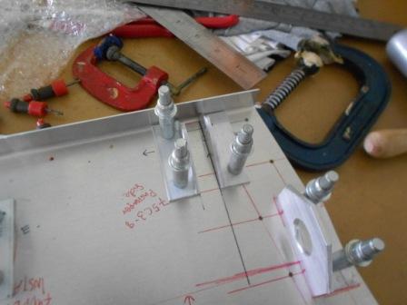
In this picture, it is shown that we have completed to pre-drill both supports for the pilot and the passenger.
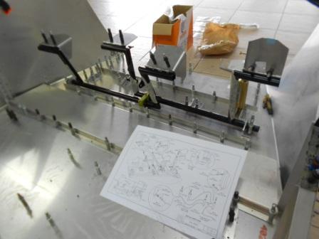
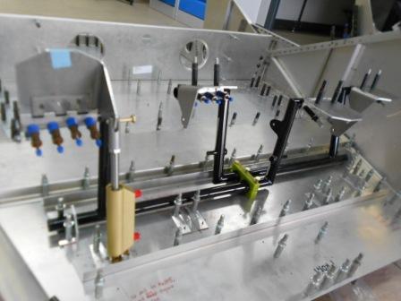
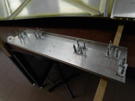
The assembly is then assembled to the forward fuselage as shown in picture above. AN3 bolt is then pre inserted to the assembly and everything is fine.