26 March 2012
FLAPERON CONTROL
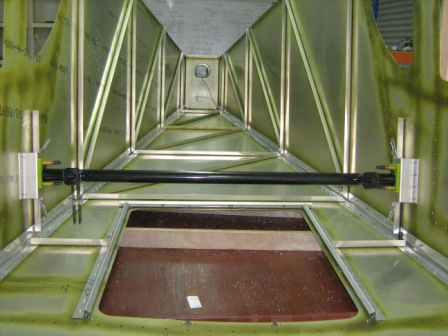
Mixer bearing (75C1-4), mixer bearing support (75C1-5) and control mixer (75C1-6) parts were identified.
Each parts were labeled and the sharp edges were deburred.
Mixer bearing was clecoed to the mixer bearing supports and the control mixer was slide into the bearings. Then,
mixer assembly was slide into position in the rear fuselage. Mixer bearing support was clecoed to the side skins.
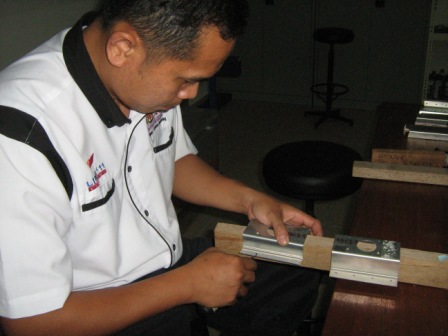
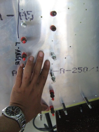
L angle was cut with a dimension of 303 mm long and then was positioned against the tab on
the right longeron and against the inside of the bearing support.
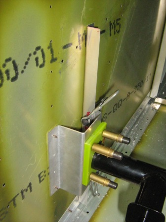
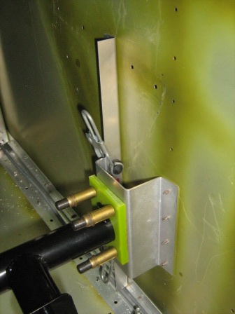
The L angle were then clamped to the right bearing support.
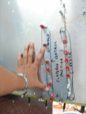
Another L angle was cut with a dimension of 303 mm long. The L angle were then positioned
against the tab on the left longeron and against the inside of the bearing support.
Then, the L angle was clamped to the left bearing support.
With a #40 drill bit, the left skin were back drilled through the L angle and clecoed.
With a #40 drill bit, the right skin were also back drilled through the L angle and then clecoed.
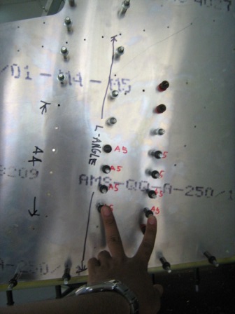
8 holes were expanded to the #20 size ( holes on the left bearing support ) through the left side skin and left upright.
Then, drilled holes were then clecoed with A5 cleco.

