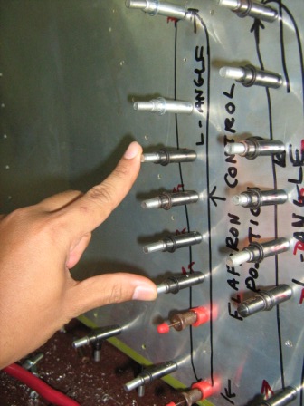
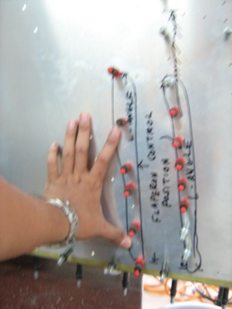
26 March 2012

FLAPERON CONTROL

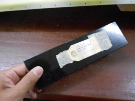
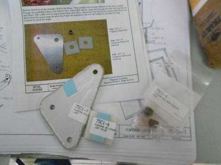
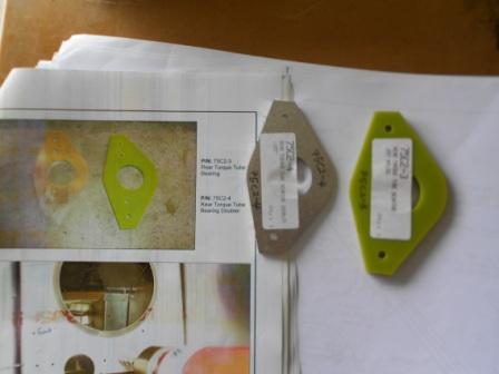
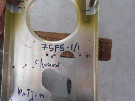
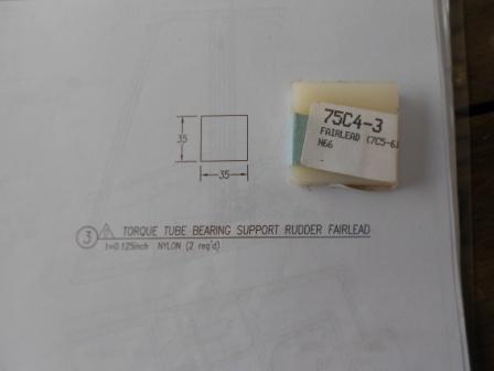
Mixer bearing (75C1-4), mixer bearing support (75C1-5) and control mixer (75C1-6) parts were identified.

Each parts were labeled and the sharp edges were deburred.

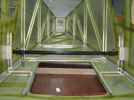
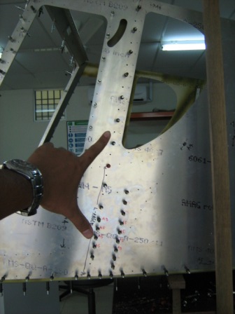
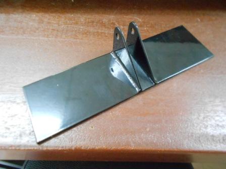
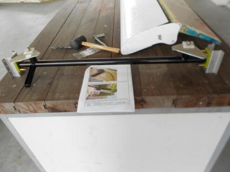
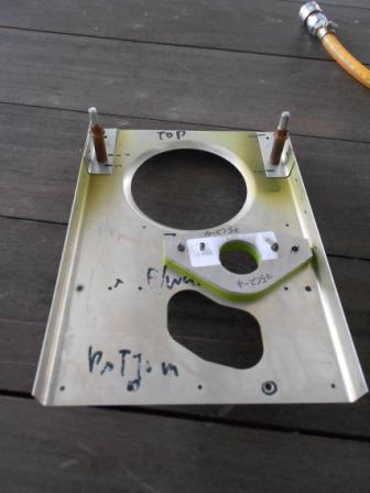
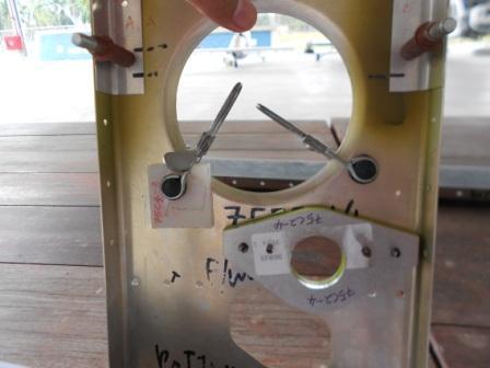
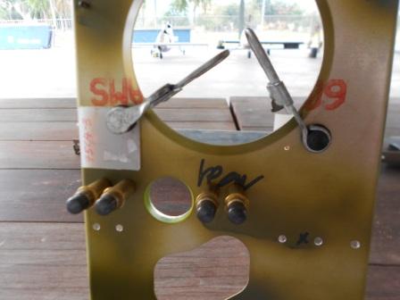
Mixer bearing was clecoed to the mixer bearing supports and the control mixer was slide into the bearings. Then,

mixer assembly was slide into position in the rear fuselage. Mixer bearing support was clecoed to the side skins.

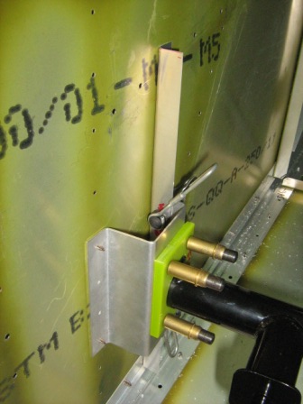
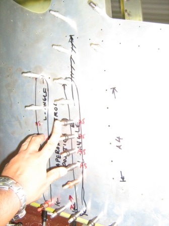
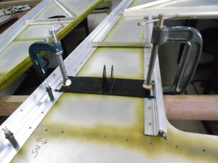
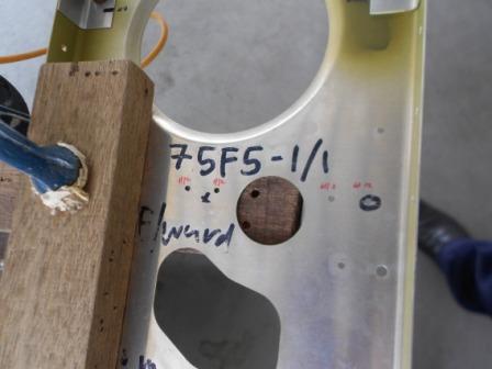
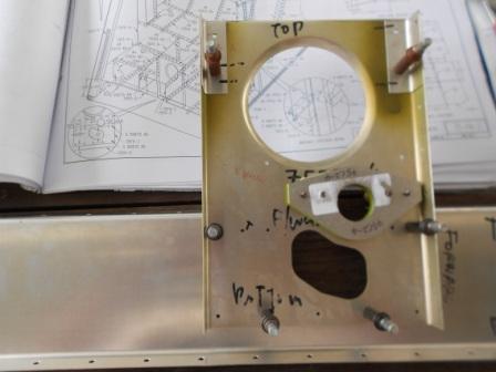
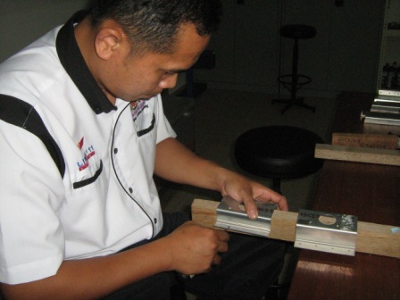
L angle was cut with a dimension of 303 mm long and then was positioned against the tab on

the right longeron and against the inside of the bearing support.

The L angle were then clamped to the right bearing support.

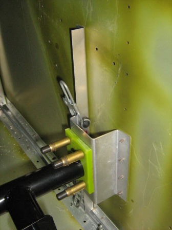
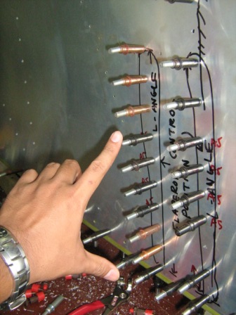
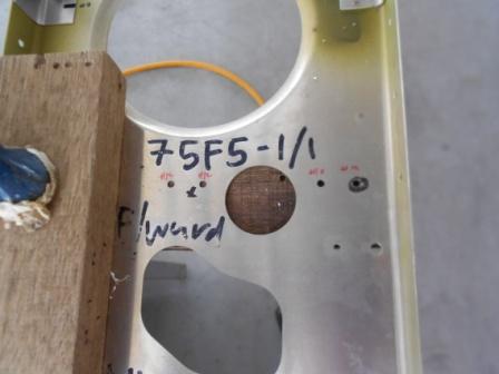
Another L angle was cut with a dimension of 303 mm long. The L angle were then positioned

against the tab on the left longeron and against the inside of the bearing support.

Then, the L angle was clamped to the left bearing support.

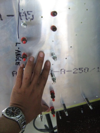
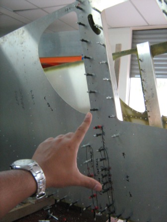
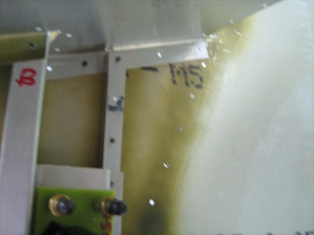
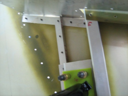
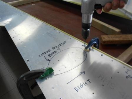
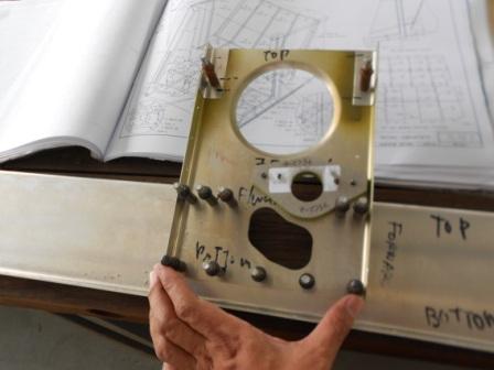
With a #40 drill bit, the left skin were back drilled through the L angle and clecoed.

With a #40 drill bit, the right skin were also back drilled through the L angle and then clecoed.

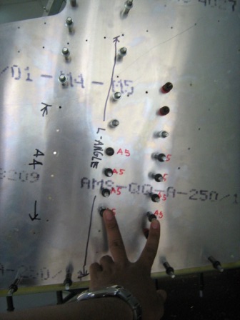
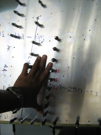
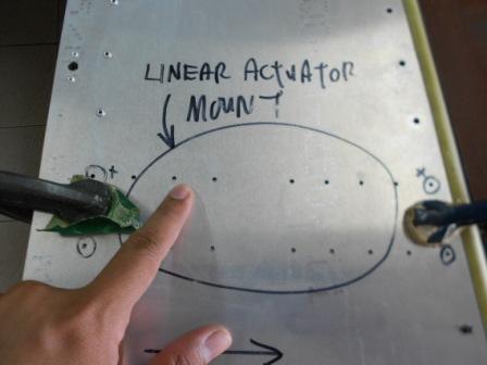
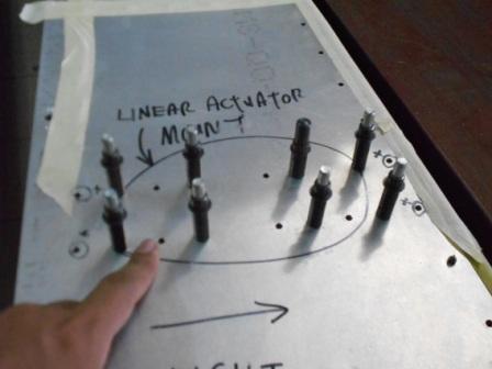
8 holes were expanded to the #20 size ( holes on the left bearing support ) through the left side skin and left upright.

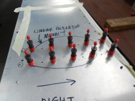
Then, drilled holes were then clecoed with A5 cleco.


27 March 2012

FLAPERON CONTROL

With a #30 drill bit, the holes were enlarged through left side skin and bearing support L angle.

#40 size holes was enlarged to #20 size holes through left side skin and through left upright (75F3-4).

#40 size holes was enlarged to #20 size holes to the right side skin through right upright (75F3-4) and bearing support.

#40 size holes was enlarged to #20 size holes to the right side skin through right upright (75F3-4).

#40 size holes was enlarged to #20 size holes to the right side skin, L angle and right bearing support.

#40 size holes was enlarged to #30 size holes through remaining holes along the L angle and right skin.

The L angle of the right bearing support was trimmed so that it fit under the baggage floor.

The L angle of the left bearing support was trimmed so that it fit under the baggage floor.


12 December 2012

FLAPERON CONTROL

This is the Linear Actuator Mount (75C1-1).We have draw a line 10mm from the aft edge (the edge towards the Linear Actuator Mounting hole).


We then positioned the Actuator Mount on the Right Side of the fuselage and clamped it with G-clamp.At first, the Actuator mount won’t fit as there is a small clash with the longerons around 1 mm.But we have solved it by filing the edge so that it will fit the space.


As shown, we have flipped the fuselage and here,as we can see the first line of holes that we need to drill through the bottom skin into the actuator mount and the longeron.


We have checked for consistency of the Actuator Mount, and here we started to drill through the Bottom Skin into the Actuator Mount and the Longeron.


Here as we can see, the holes are drilled with #40 drill size and gripped with #40 grip pin, shown in red.


Then, we continue to enlarge the holes into #20 drill bit as instructed in the Plan and Photo Assembly Manual. No issues for this part.The actuator mount is then unassembled and the holes on the Actuator Mount and Bottom Fuselage are debured.We then clean up the burrs and undercoat the Actuator Mount with Black Can Spray to protect the bare metal from corrosion with respect to time.


Here, we have started to work on the other parts of the flaperon controls. We started by identifying the parts that is Flaperon Bellcrank (75C1-7), Flaperon Bellcrank Bearing (75C1-8) and Flaperon Bellcrank Bushing (75C1-9). As we can see in the picture, Flaperon Bellcrank Bushing (75C1-9) has surface corrosions. We have done maintenance on the parts that was removing the corrosion, and spraying it with LPS-3.


We then marked the center of the Flaperon Bellcrank Bearings (75C1-8), as shown in the picture.


With a #40 drill bit, we then drill a hole in the center of the bearing.We then expanded the hole up to ½” in steps. We also have clamped the bearing in a vise to prevent it from spinning while drilling the holes.The Flaperon Bellcrank is then filed so that no sharp edges on every edges.


13 December 2012

FLAPERON CONTROL

Then, we identified the hole that needs to be expanded, circled with black pen in the picture.


We then use a step drill, with a ½” drill bit to expand the mounting hole in the Flaperon Bellcrank.We do it on both sides. We have checked drawing 75-C-1 for the specific hole.We have done it to both of the Flaperon Bellcrank and no issue about this.


As in the photo assembly manual, we have make sure that the Flaperon Bushing should turn freely in the Bellcrank, and make sure that the hole is large enough for it to turn but not be too loose. At this point, we did not grease the outside of the Bushing and the faces of the Bearings that contact the Bellcrank. We only coated the Flaperon Bushing with LPS-3, rust inhibitor for now.

We then slide the bushing on the stud of the mixer. We did not yet put grease on the plate on the Mixer at this time and installed the first bearing followed by the Bellcrank and Second Bearing. We have half tighten the Castle Nut on the Stud for pre assembly.


9 January 2013

FLAPERON CONTROL

As for today, we have continue to installing the Rear Torque Tube Bearing (75C2-3) and Rear Torque Tube Bearing Doubler (75C2-4).We identify the parts and checked the part number is correct with the photo manual.


The manual ask us to use a #12 drill bit to expand the holes in the Torque Tube Bearing Support for the Tube Bearing.At first, we have identified the 4 holes that need to be enlarged to #12 drill bit. We then marked the holes with red sharpie.Clamp the Torque Tube Bearing Support on the working table.We will drill step by step to enlarge the holes.We then enlarge the holes to #30 size with a #30 drill bit.


With a larger drill bit #20, we then enlarge the 4 holes with a #20 drill bit. The Torque Tube Bearing Support still in a fixed position as clamped before. The holes are checked for any crack and no any crack is detected.


We then finally enlarged the holes into #12 drill size as in the photo manual instruction. We then use a slightly larger drill bit to remove the burrs.


Then we fitted the Rear Torque Tube Bearing Support (75C2-3) and Rear Torque Tube Bearing Doubler (75C2-4) with A6 cleco.


Then we install the Torque Tube Bearing Support to the Torque Tube Bearing Channel (75-F4-5).The assembly is checked with consistency of the drawing.Then, we are going to enlarge the holes that not yet enlarge to #20 that are shared by both parts.


With a #20 drill bit, we then enlarge the holes into #20 hole size as noted in the drawing.The holes are then deburred and checked for any cracks and no cracks detected.


We now move on to the Torque Tube Bearing Support Rudder Fairlead. That is 75C4-3.


These fairleads will be install on the two locations as clamped in the pictures above.


Above is the picture for the backside of the Torque Tube Bearing Support. Today we only done for the fitting purposes and no other operations being made to the parts.


  • 1
  • 2