
9 January 2013
FLAPERON CONTROL
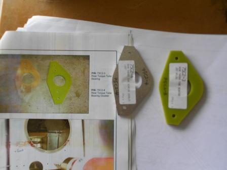
As for today, we have continue to installing the Rear Torque Tube Bearing (75C2-3) and Rear Torque Tube Bearing Doubler (75C2-4).We identify the parts and checked the part number is correct with the photo manual.
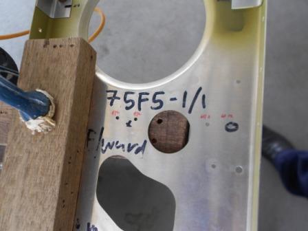
The manual ask us to use a #12 drill bit to expand the holes in the Torque Tube Bearing Support for the Tube Bearing.At first, we have identified the 4 holes that need to be enlarged to #12 drill bit. We then marked the holes with red sharpie.Clamp the Torque Tube Bearing Support on the working table.We will drill step by step to enlarge the holes.We then enlarge the holes to #30 size with a #30 drill bit.
With a larger drill bit #20, we then enlarge the 4 holes with a #20 drill bit. The Torque Tube Bearing Support still in a fixed position as clamped before. The holes are checked for any crack and no any crack is detected.
We then finally enlarged the holes into #12 drill size as in the photo manual instruction. We then use a slightly larger drill bit to remove the burrs.
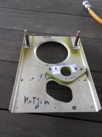
Then we fitted the Rear Torque Tube Bearing Support (75C2-3) and Rear Torque Tube Bearing Doubler (75C2-4) with A6 cleco.
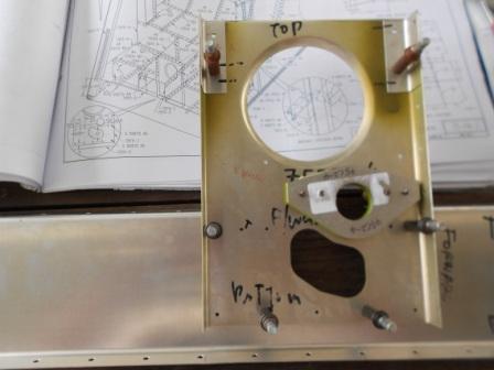
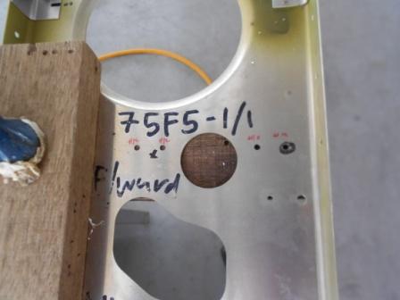
Then we install the Torque Tube Bearing Support to the Torque Tube Bearing Channel (75-F4-5).The assembly is checked with consistency of the drawing.Then, we are going to enlarge the holes that not yet enlarge to #20 that are shared by both parts.
With a #20 drill bit, we then enlarge the holes into #20 hole size as noted in the drawing.The holes are then deburred and checked for any cracks and no cracks detected.
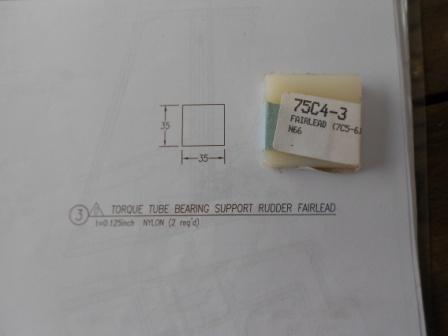
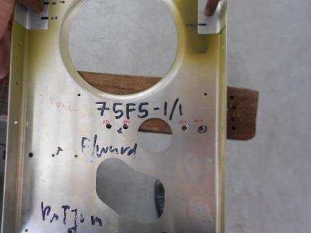
We now move on to the Torque Tube Bearing Support Rudder Fairlead. That is 75C4-3.
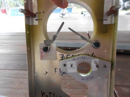
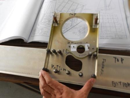
These fairleads will be install on the two locations as clamped in the pictures above.
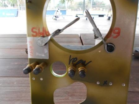
Above is the picture for the backside of the Torque Tube Bearing Support. Today we only done for the fitting purposes and no other operations being made to the parts.