
9 August 2012
FUSELAGE JOINING & FORWARD FUSELAGE SECTION
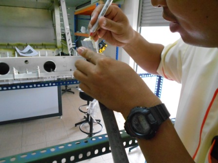
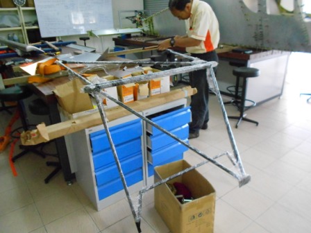
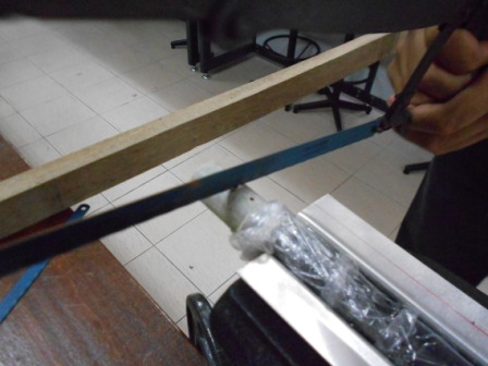
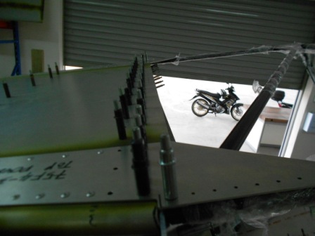
We measured the distance between the Right Rear Wing Attachment and the first hole in the Top Doubler for Right Side Fuselage as shown in the picture. And then we measured the distance between the Left Rear Wing Attachment and the first hole in the Top Doubler for Left Side Fuselage.
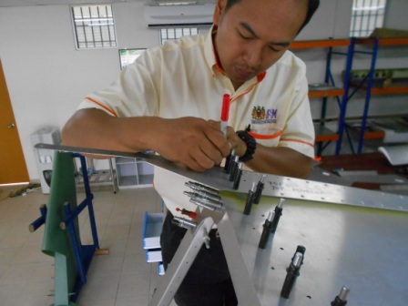
Then, we marked the measurement in the previous step to the Cabin Frame (75F15-1) Top Rear Left Tube from the pilot hole.
Then, we marked the measurement as also in the previous step to the Cabin Frame (75F15-1) Top Rear Right Tube from the pilot hole as shown in the picture.
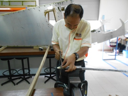
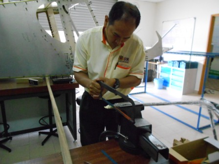
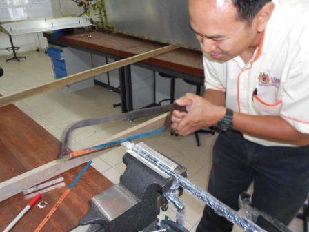
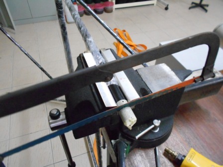
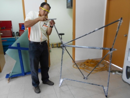
Next, with a Hacksaw, we have trimmed the excess material of the Cabin Frame (75F15-1) Top Rear Left Tube. The trimming line is vertical for now. The Cabin Frame is clamped with a table G- clamp so that there will be no problem when trimming the tube. The bottom of the Cabin Frame (75F15-1) is supported by a box to make sure the top of the Cabin Frame is horizontal.
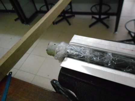
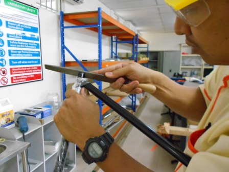
Shown in the picture, the Cabin Frame (75F15-1) Top Rear Left Tube was trimmed and with a file, we have smoothed the edge from burrs. We also make sure that the edge is free from trimmed marks.
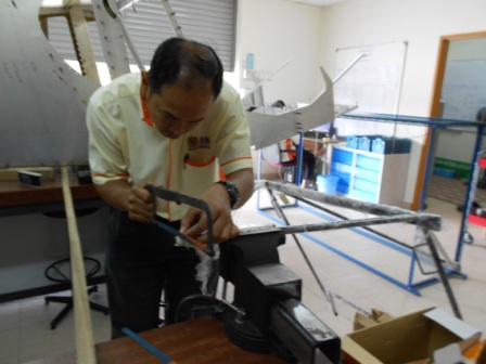
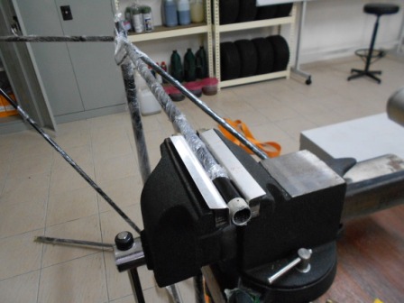
Then, we continue to trim the Cabin Frame (75F15-1) Top Rear Right Tube with a hacksaw. The trimming line is vertical for now. The Cabin Frame is clamped with a table G- clamp so that there will be no problem when trimming the tube. The bottom of the Cabin Frame (75F15-1) is supported by a box to make sure the top of the Cabin Frame is horizontal. Then, the Cabin Frame (75F15-1) Top Rear Right Tube was trimmed and with a file, we have smoothed the edge from burrs. We also make sure that the edge is free from trimmed marks.
Then we measured the distance between the first hole to the Right Front Longeron Cabin Side.
Then, we measured the distance between the first hole to the Left Front Longeron Cabin Side.

Then we marked the distance measured in the previous step from the first hole at the Cabin Frame Left Vertical Tube.
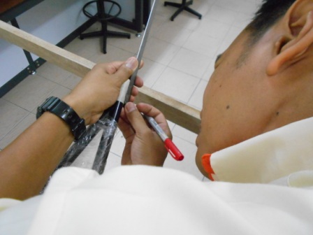
We also have marked the distance measured in the previous step from the first hole at the Cabin Frame Right Vertical Tube.
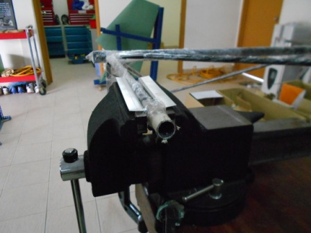
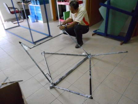
Then, we clamped the Cabin Frame Left Vertical Tube with a G- Clamp and two L-Angles to undamaged the tube. With a hacksaw, we trimmed the mark vertically. No angle trimming for now.
The trimmed tube is then smoothened with a file to remove cutting marks and burs
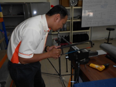
Then, we clamped Cabin Frame Right Vertical Tube with a G- Clamp and also two L- Angles to undamaged the tube. With a hacksaw, we then trimmed the tube vertically, as no trimming angle is done for now.
Then the trimmed Cabin Frame Right Vertical Tube is then smoothened with a file to remove cutting marks and burs.
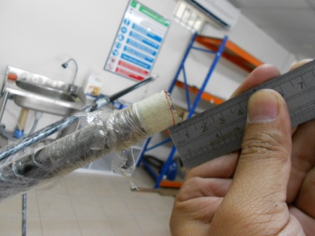
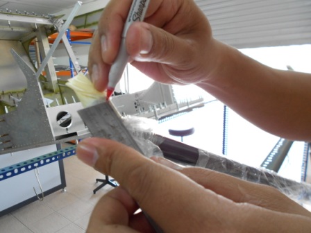
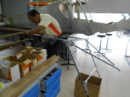
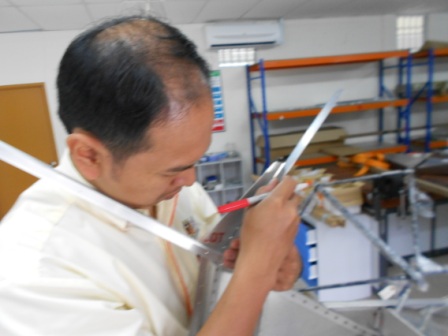
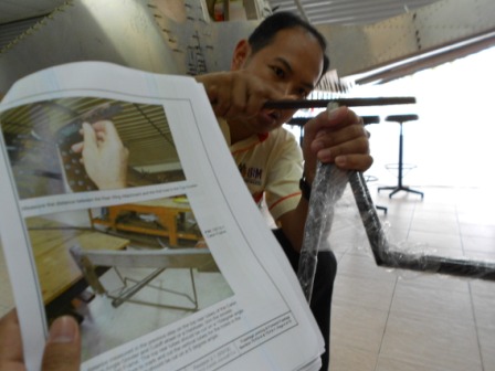
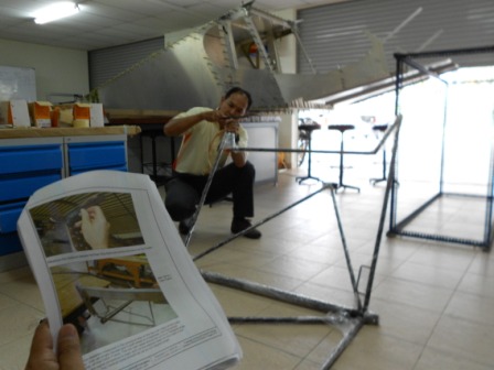
We then installed the Cabin Frame into the Forward Fuselage and measured the clearance between the edge of the tube and the Rear Wing Attachment. Because one edge is touching the Rear Wing Attachment, so, we decided to measure the clearance of the other edge on the same tube so that we will have a good angle. 5 mm is the measured distance and the distance is then marked to the Cabin Frame Left Top Rear Tube as shown in the picture. Then we also have drawn a line that is from the top edge of the tube to the marked line before. Noted in the photo assembly manual stated that the best angle is 15 degrees.
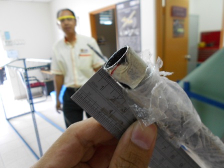
Then, we have also transfer the measurement to the Cain Frame Left Top Rear Tube that is also 5 mm distance between the bottom edge to the mark. Then we also have drawn a line that is from the top edge of the tube to the marked line before.
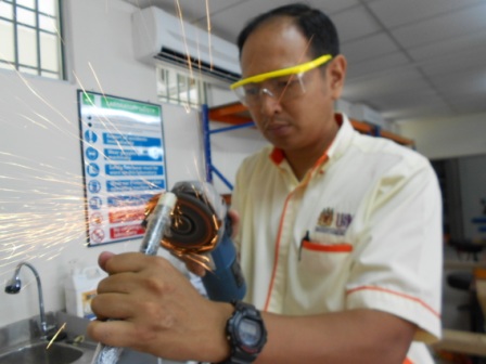
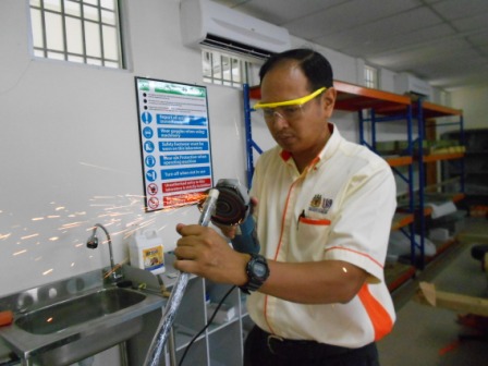
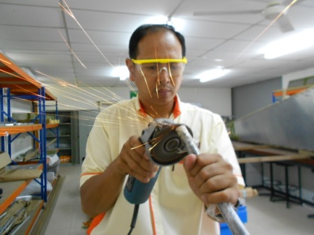
Using a grinder, we then trimmed the Cabin Frame Right Top Rear Tube to the marked line.
Then, same operation is done to the Cabin Frame Left Top Rear Tube to the marked line.
Then we file the trimmed edge to remove the trimmed marks and burrs.
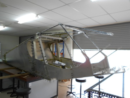
Then, we assemble the Cabin Frame to the Forward Fuselage. Both two holes on the Cabin Frame are successfully aligned with the Rear Fuselage Top Doubler and clecoed with #40 clecos. We then measured the Vertical Tubes so that the hole in the vertical tube is aligned with the Pre-drilled holes in the Forward Cabin Side Skin (75F7-1).
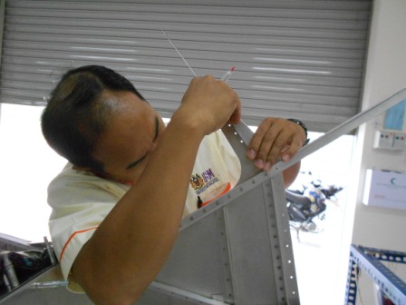
With a file, we then file the excess material on the Cabin Frame Right Vertical Tube so that it will match the Forward Cabin Side Skin.
With a file, we then file the excess material on the Cabin Frame Left Vertical Tube so that it will match the Forward Cabin Side Skin.
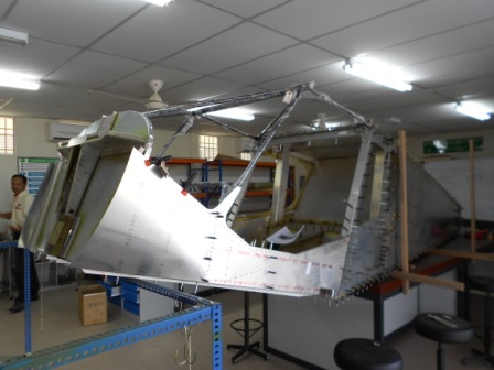
Then, we assembled the Cabin Frame to the Forward Fuselage. Both Vertical Tube pilot holes are aligned with the first pre-drilled hole in the Forward Cabin Side Skin (75F7-1). And also, as in previous steps, we also managed to re cleco the Top Rear Tubes Cabin Frame to the Top Doubler. Then we preinstalled the Firewall and Forward Side Skin to the fuselage. The firewall angle is 100 degrees, with respect to the cabin floor as we measured it with a digital protractor with the top of the firewall is leaning to the Forward Tube of the Cabin Frame. From the result, we managed to get the right angle as in the plan.
- Hits: 299