
1 November 2012
FUSELAGE JOINING & FORWARD FUSELAGE SECTION
Today, we have un assembled the (75F3-6) Top Channel and (75F4-1) Side Channel and 75F4-4 (Right and left Wing Attachment) from the Rear Fuselage Assembly as in the log report dated 19/10/2012, the (75F4-3) Top Doubler, both left and right have limit our drill tool to drill the most upper holes on the 75F4-4 (Wing Attachments both left and right.)
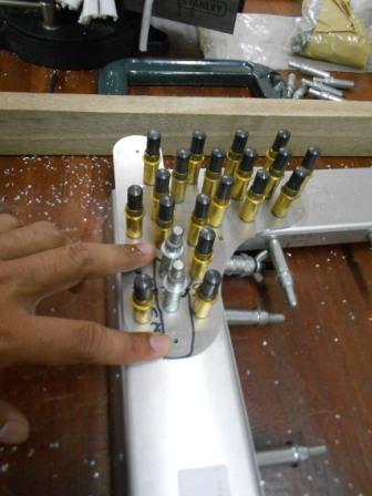
Then we secure most of the hole with #40 clecos and 3/16” clecos in gold. All the holes are check and must be parallel to each of the parts. And for this step, we will start drilling with A6 drill size on the silver clecos that is still pilot holes.
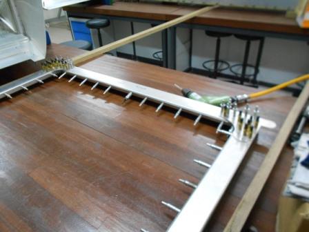
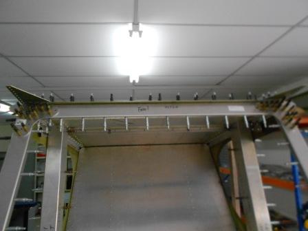
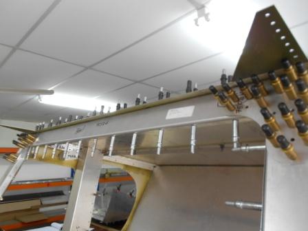
As the Top Channel is assembled to the wing attachment and Rear Top Channel (75F3-7), there are some gap between the Top Channel and rear Top Channel. To make the assembly rigid, we put a thin wood between both of the parts and it helps to put the assembly in a steady position. And then, we start drilling the A6 rivet holes with 3/16” drill size. As in the picture we have left out three holes that are clecoed with silver clecos. These will be done later.
Then we move on to the Passenger Side Wing Attachment. We then continue to drill the remaining pilot holes to A6 with 3/16” drill bit. We also positioned a thin wood around ½ inches to fill the gap between the Top Cover and Rear Top Cover. As also shown in the picture, we have left three holes that are clecoed with silver clecos and will be done later.
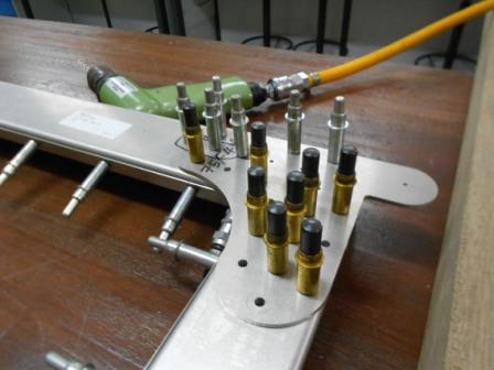
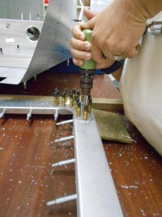
Then, we are ready to drill the hole for the AN3-5A bolt. As in the Construction Standards, page 8 of 42, Draft Edition (07/09/07) 1985-2007, these bolts need a hole with size 3/16”. So, we have located three holes that need to be drill with 3/16” drill size.
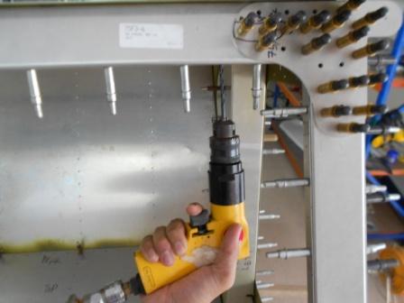
With a 3/16” drill bit, we then enlarged the three holes that is for the AN3-5A bolts on the Pilot Side/ Left Side Wing Attachment through the Top Channel.
As in the picture, we have drilled the hole to the required size that is 3/16” and clecoed it with 3/16” clecos.
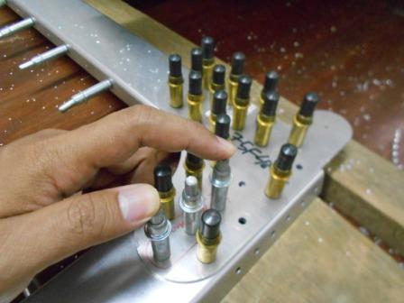
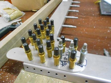
And now we move on to the passenger side and as shown in the picture, these three holes will be enlarged for AN3-5A bolts with 3/16” drill bit. We also maintained the positioned of the thin wood between the Top Channel and Rear Top Channel so that the assembly is rigid for drilling.
Then with a 3/16” drill bit, we enlarged the holes. The holes were clecoed after enlarged with 3/16” clecoes.
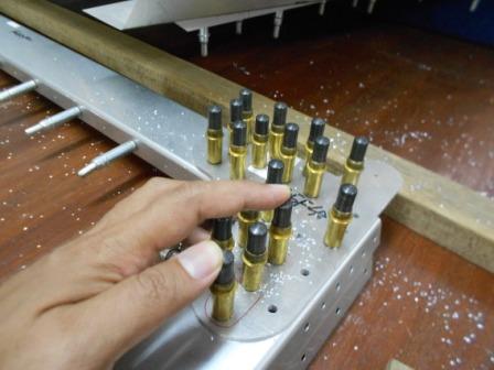
As shown in the picture, the three holes have been enlarged to 3/16” holes size.
We then assembled the Top Channel, Wing Attachment and Side Channel to the Rear Fuselage and clecoed them with required size clecos.
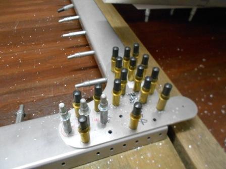
Now, we move on to the Top Channel (75F3-6) and Rear Top Channel Assembly (75F3-7). As in the plan, the plan calls for A5 rivet, that 5/32” hole size. We then checked the silver clecos so that all are tight and parallel to each other. We also checked the all the holes are aligned between the Top Channel and the Rear Top Channel.
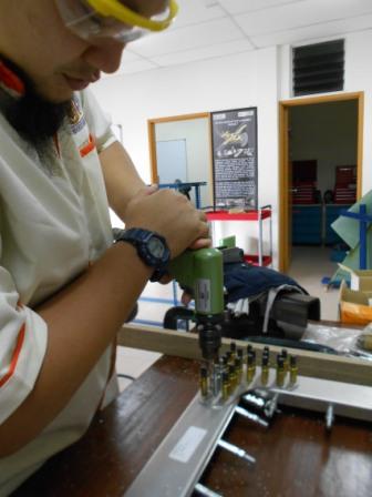
With a #20 drill bit, we then started to enlarge the holes.
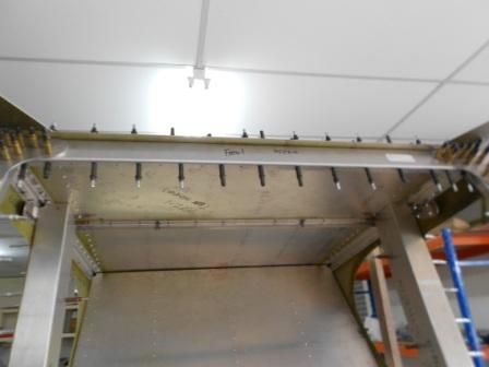
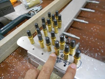
As shown in the picture, the Top Channel and Rear Top Channel pilot holes have been enlarged to A5 hole size and clecoed with #20 clecos in black. All holes are fine and no issue on this work.
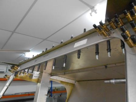
As in this picture, we can see the enlarged holes are clecoed with #20 clecoes that is in black colour. No issue for today.
- Hits: 71