
19 October 2012
FUSELAGE JOINING & FORWARD FUSELAGE SECTION
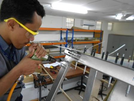
Today, we plan to enlarge the pilot holes that are connecting the Forward 75F1-1 (Bottom Fuselage Skin) and 75F10-1 (gear Channel). The holes are clecoed with #40 clecos (silver colours)
The angle of the fuselage has been checked.
And with a new #20 drill bit, we then enlarge the #40 holes. Each hole is clecoed with #20 cleco and made sure that all clecoes are tight.
This another view of the enlarged holes with #20.
We then examined the connection between the 75F-7 (Left Cabin Side), through 75F4-2 (Side Channel Cover) and 75F1-3 (Fuselage Side Skin) to be enlarged with #20 drill bit. All holes are then clecoed with #40 cleco to hold both parts. As there are two pilot holes line vertically side by side, the other one is between the 75F1-3 (Fuselage Side Skin) and 75F4-2 (Side Channel Cover). These pilot holes also will be enlarged with #20 drill bit. Each of the holes are clecoed with #40 and the holes are checked for consistency.
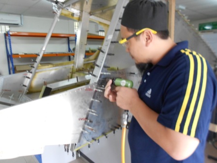
With a #20 drill bit, we then drill from top to bottom and each enlarged holes are clecoed with #20 cleco. We also made sure that we drill it straight through the parts.
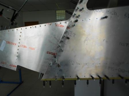
As shown in the picture, we have drilled the parts and clecoed the holes with #20 drill bit for the left side fuselage. No problem with the drilling on these parts.
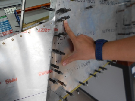
Then, we examined the right fuselage and the holes that will be enlarged. The enlarging are applicable to 75F-7 (Left Cabin Side), through 75F4-2 (Side Channel Cover) and 75F1-3 (Right Fuselage Side Skin) that will be enlarged with #20 drill bit. All holes are clecoed with #40 cleco to hold both parts. As there are two pilot holes line vertically side by side, the other one is between the 75F1-3 (Fuselage Side Skin) and 75F4-2 (Side Channel Cover).
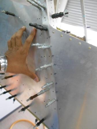
After we have drilled with #20 drill bit, we then clecoed the holes with #20 clecos shown black in colour. G clamp is used to minimize the expansion of the left cover with left side fuselage skin. There are no issues of the drilled holes.
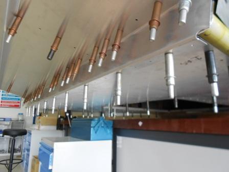
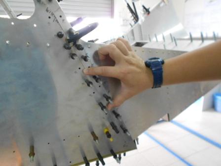
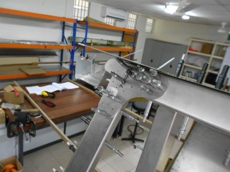
Now we move on to 75F4-4 (Wing Attachment - Left). This attachment is attached to 75F3-6 (Top Channel) and 75F4-1 (Side Channel) and the same for the right side. In the plan, the plan calls for 12 + 9 Rivets A6, and 3 Bolts AN3-5A. We have rounded with a black marker of three holes that will be fitted with AN3-5A Bolts.
We clecoed the 75F4-4 (Wing Attachment - Left) with #40 clecoes so that the part is tight with 75F3-6 (Top Channel) and 75F4-1 (Side Channel). The Top Channel and Side Channel is also clecoed so that the frame is in normal position. The pilot holes on the Wing Attachment are checked and are parallel with the Pilot holes on the Top Channel and Side Channel.
As the plan calls for A6 rivet, so we have drilled the pilot holes with new 3/16” drill bit. But only most of the holes on the bottom of the wing attachment is enlarged as the 75F4-3 (Top Doubler) has limit our drill tool, so we will not enlarge the top portion of the Wing Attachment yet. We decided to take off the Wing Attachment together with Side Channel and Top Channel after we have finished enlarging the holes to 3/16” on the other side. The clecos for 3/16” are different from others as the clecos are in gold colours.
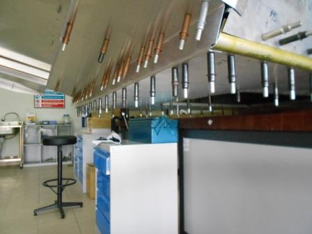
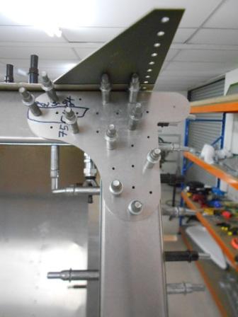
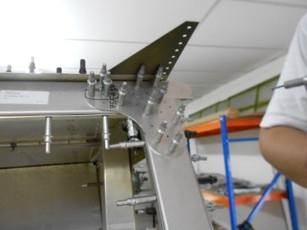
Now we move on to the right side of the fuselage wing attachment. As we can see here, most of the holes are clecoed with #40 clecos through the Wing Attachment – Right, Top Channel and Side Channel. Both Top Channel and Side Channel are also clecoed with #40 cleco. The pilot holes on the wing Attachment are also checked so that all the holes are parallel with the Top Channel and Side Channel before we started cleco the parts. The pilot holes for AN3-5A Bolts are marked with Red Marker and clecoed so that those holes are not accidentally enlarged with 3/16” drill bit.
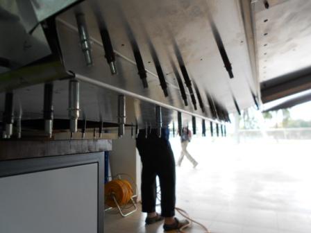
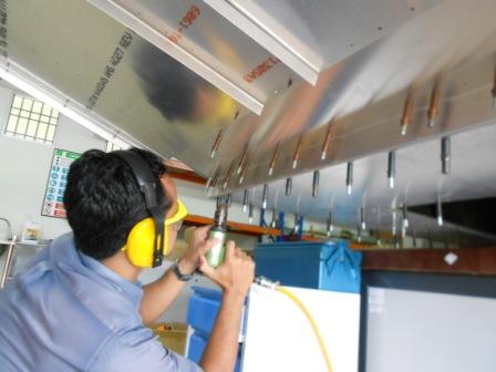
With a 3/16”, carefully, we enlarge the pilot holes on the wing Attachment through the Side Channel and Top Channel. The drill bit is made sure to be perpendicular to the surface so that it will be a perfect hole. Every bur is then remove from the drilled hole before the holes are clecoed with the 3/16” clecos.
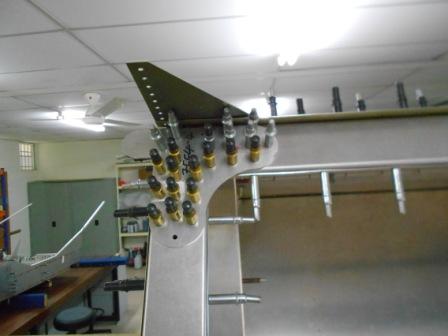
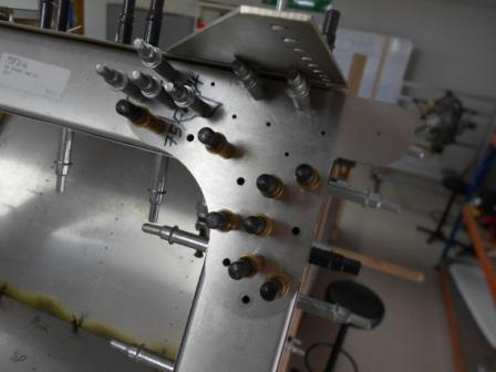
As shown in the picture above, the enlarged holes are clecoed with 3/16” clecos. Most of the enlarged holes are at the bottom of the wing attachment as the Top Doubler is limiting our drill tool. After this, we will take off the assembly, and continue to enlarge the pilot holes with 3/16” drill bit.
- Hits: 70