
16 May 2013
FUSELAGE JOINING & FORWARD FUSELAGE SECTION
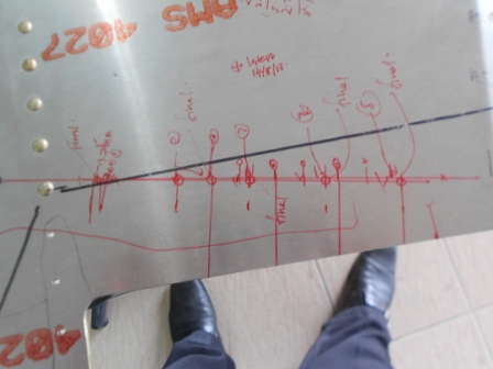
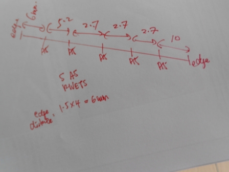
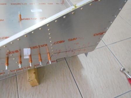
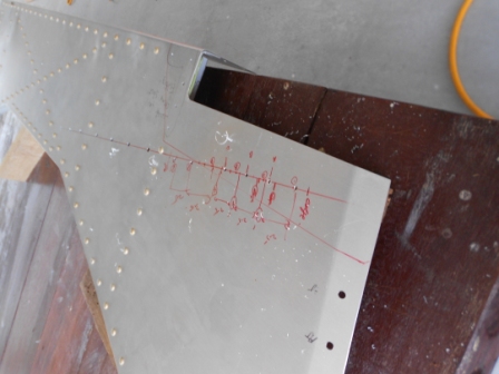
As for today, we have finalized the position of the Gear Strut Fitting on the Both Side Fuselage. A black line is drawn for the along the edge of the Gear Strut Fitting. Then, a red line is then marked along the rivets from the Seat Base on the Side Fuselage. 5 A5 holes are then layout along the line as shown in the picture above. The latest hole is as shown above.
The layout of the holes is shown as in the picture above.
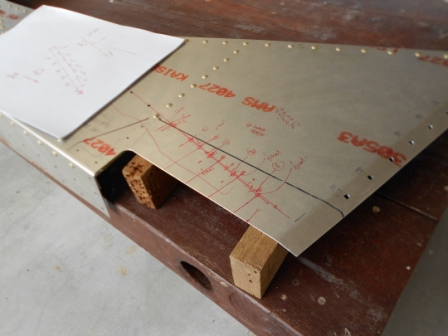
The Left Side Fuselage is then lay on the bench and ready for drilling to #40 hole rivet.
With #40 drill bit, we then drill 5 #40 holes through the Left Side Fuselage.
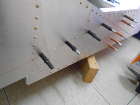
The Left Side Fuselage is then installed to the Forward Fuselage.
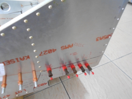
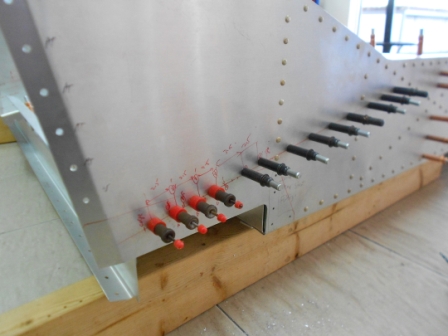
With #40 Grip pin, we then gripped the Left Side Fuselage with the Seat Base.
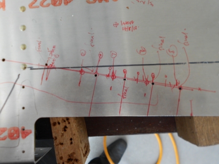
Then, as shown in the picture above, we will enlarge the A4 rivets into A5 holes.
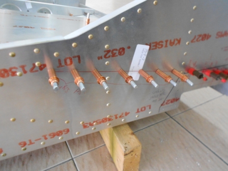
Then, with A5 drill size, we enlarged the previous A4 holes, and also two holes on the aft portion. In this process, we have added on 1 more additional rivet on the aft portion of the Seat Base. This is because, on the first fitting of the Gear Strut Fitting, we have wrongly positioned the Gear Strut Fitting. The plan call for the front side of the Gear Strut Fitting to be aligned with the Bottom of the Forward Fuselage, but we accidentally positioned it align with the skin edge of the Forward Fuselage. Therefore, when we try to make correction, the Gear Strut Fitting is positioned a bit lower than the original location therefore makes the area of the fitting to be more spaces.
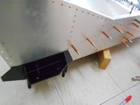
Then we move on to the Right Side Fuselage. We positioned the Gear Strut Fitting as shown in the picture. Then we draw a line along the side of the Gear Strut Fitting.
We then remove the Gear Strut Fitting, and enlarged the A4 holes into A5 size hole with #20 drill bit and cleco.
After we have unassembled the Right Side Fuselage, we then drill the aft with #40 drill bit with 6 holes.
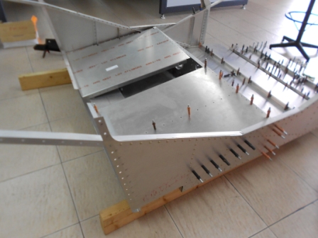
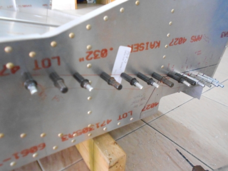
Then, we assembled the Right Side Fuselage and clecoed and fastened it with #20 clecos along the Seat Base.
With #40 grip pins, we then fastened the Right Side Fuselage to the Seat Base. And we also enlarged two holes on the aft portion with A5 drill bit. Actually, in the plan, it asked the builder to lay out 5 holes on the aft portion of the seat base. But within the calculation of the pitch, the aft portion need 6 rivet holes, therefore we have layout 6 holes on the aft portion. On this point, we have positioned the Gear Strut Fitting as in the plan.
- Hits: 75