
17 June 2013
FUSELAGE JOINING & FORWARD FUSELAGE SECTION
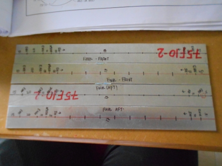
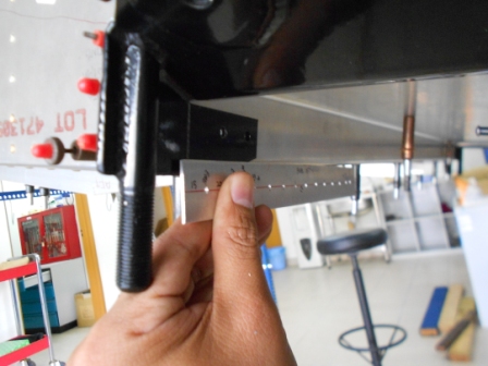
As for today, we will start the process to install the Gear Channel Doubler (75F10-2). The photo guide asked us to layout total of 10 A5 rivets, 1 AN3-3A and 1 AN3-4A hole. As in the picture on top, we have located one hole for AN3-4A bolt, which is 15mm from the edge. Then we locate the other AN3-4A, 20 mm from the previous hole. Then, we locate 10 mm from the second hole as the edge and marked. First A5 rivet hole is located 10 mm from the edge marked before.
We also marked 1 AN3-3A hole 15 mm from the end of the other edge. Second A5 rivet is also marked 10 mm from the AN3-3A hole. Then, 8 more rivets are layout evenly spaced using a Rivet Fan.
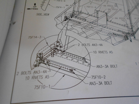
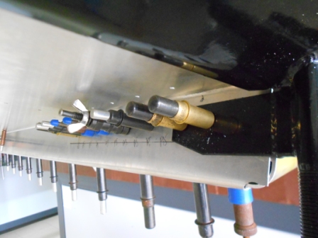
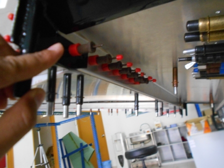
This picture presents the work to complete the process of installing the Gear Channel Doubler.
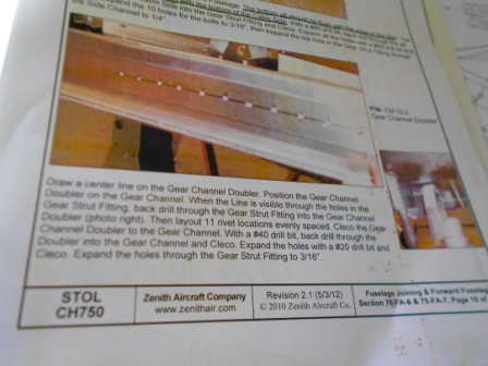
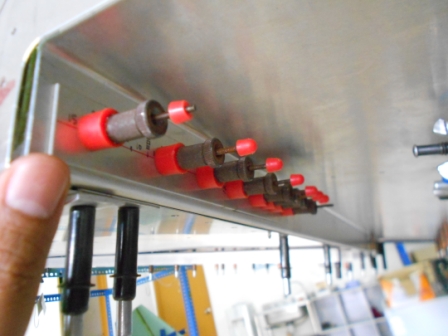
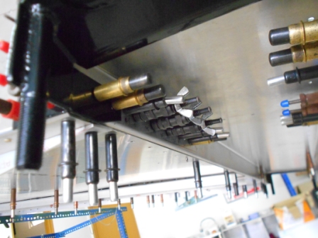
This picture presents the hole that need to be drilled through the Gear Channel Doubler.
We have started to install the Gear Channel Doubler on the Pilot Side. As in the picture, we have drilled the Gear Channel Doubler with #40 rivets on every point except the second AN3-4A hole on the Gear Strut Fitting. We also have drilled the first AN3-4A hole on the Gear Strut Fitting with #40 drill bit through the Gear Channel. The Gear Channel Doubler is then clecoed on the Gear Channel. With a #40 drill bit, we then drill through the Gear Channel Doubler to the Gear Channel.
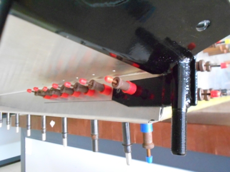
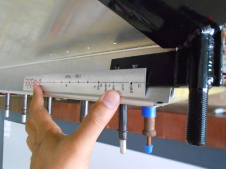
We then install the Gear Channel Doubler inside. We then Grip pin both parts with #40 grip pin. With a #40 drill bit, we then drill through the second AN3-4A hole on the Gear Strut Fitting and grip pinned.
With a 3-16 drill bit, we then enlarged holes as required in the plan. We also have enlarged the ten holes with #20 drill bit. The holes are gripped with temporary fasteners with respect to their holes sizes.
Next, we started to install the Channel Doubler for the front part of the Pilot Side. As previous, we have pre drill the Channel Doubler, except the second AN3-4A hole on the Gear Strut Fitting. And also we have pre-drilled through the first AN3-4A hole and the Gear Channel.
We then remove the Gear Strut Fitting, then cleco the Channel Doubler to the Gear Channel. After we have measured the Channel Doubler so that it is positioned horizontally, we then drill through the Channel Doubler and the Gear Channel except the second hole on the Gear Strut Fitting.
Then, we install the Channel Doubler to the inside Gear Channel. With a #40 drill bit, we then drilled through the second AN3-4A hole on the Gear Strut Fitting through the Gear Channel and cleco.
With a 3-16 drill bit, we then enlarged holes as required in the plan. We also have enlarged the ten holes with #20 drill bit. The holes are gripped with temporary fasteners with respect to their holes sizes.
- Hits: 179