
22 May 2013
FUSELAGE JOINING & FORWARD FUSELAGE SECTION
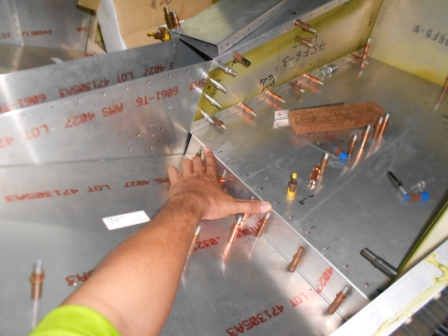
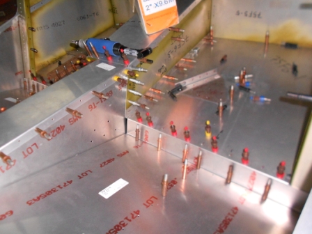
Today we will start to join the Forward Fuselage with the Rear Fuselage. The Seat Base is installed on both sides as shown in the picture. Then the Seat base needs to be drilled through the Lower Baggage Floor on the Right and Left Side of the fuselage. As you can see, there is an opening, at the centre of the picture, as shown, we have contacted technical support of the Zenith Aircraft Company and the advised us that it is just fine with it. Just leave as it is.
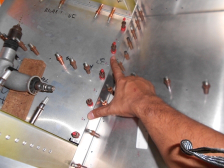
Next we started on the Passenger Side, we have drilled through the Right Lower Baggage Floor, 75F6-1, and the Right Seat Base with #40 drill bit and gripped with #40 grip pin.
Then we need to drill few holes through the Right Control Tunnel Side, 75F6-2, and Right Arm Rest Side, 75F11-6, with #40 drill bit.
As shown in the picture, we have drilled the both parts with #40 drill bit and gripped with #40 grip pin.
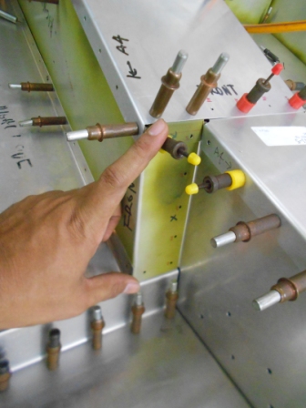
Then with #40 drill bit, we then drilled through the Left Seat Base and the Left Lower Baggage Floor. The holes are then clecoed with #40 grip pin.
Then we enlarged the previous #40 holes to A4 holes with #30 drill bit as in the plan. All the holes are then clecoed.
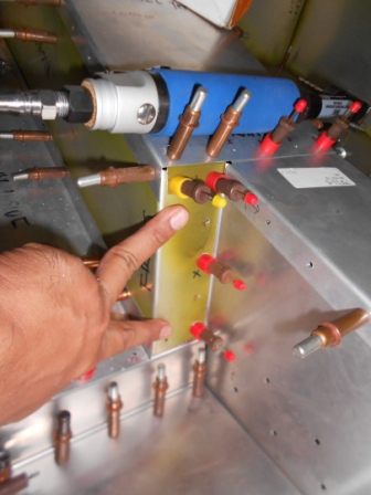
Then we enlarge all previous #40 holes with #30 drill bit and cleco each hole staggered.
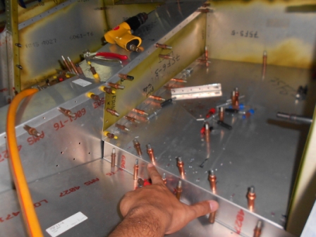
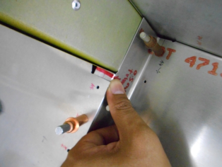
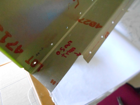
In our assembly, we detected that we need to trim 5/16 inch of the seat base clearly shown as in the picture above to give more clearance to side fuselage to go inward.
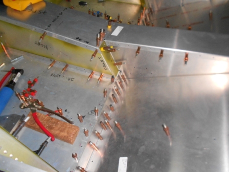
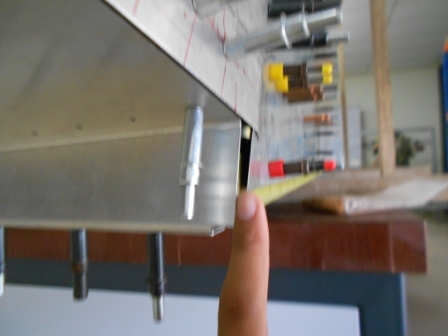
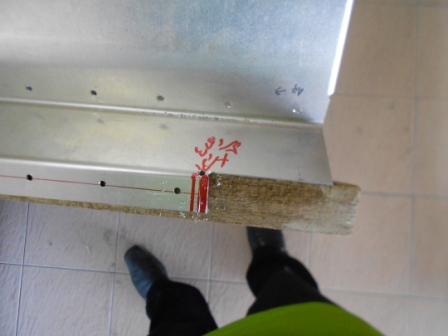
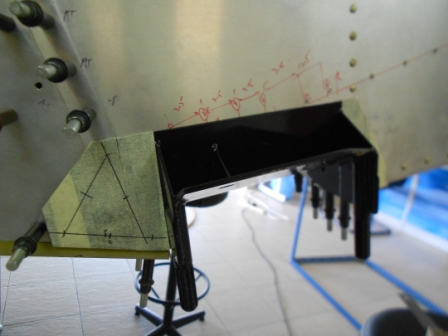
This picture is from the bottom view of the Right Side Fuselage. As in the picture, it is clearly shown that the Gear Strut Fitting is stopped on the Side Channel Cover, 75F4-2 and Side Channel, 75F4-1.
It also the same on the Left Side Fuselage. We need to trim 0.5 mm to the seat base to give clearance to the Left Side Fuselage, Left Side Channel and Left Side Channel Cover to go inward.
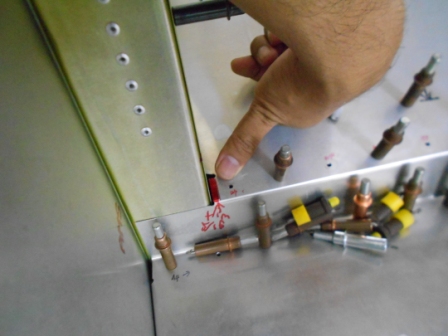
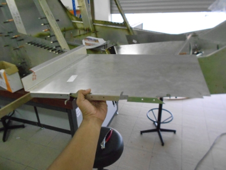
As shown in the picture, it is clearly shown that the Left Side Fuselage have a gap.
So we have trimmed the Seat Base as shown in the picture. A lightening corner using A5 drill bit is done to the edge of the trimmed area.
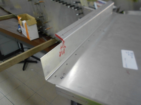
Then we will trim the Right Seat Base of the Right Side Fuselage.
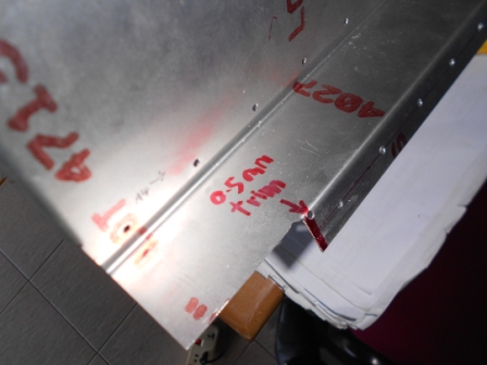
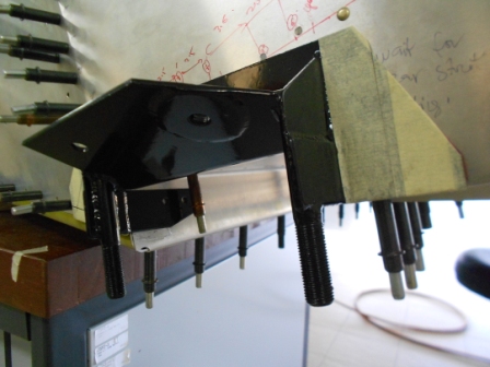
As shown in the picture we have trimmed the Right Seat Base and apply a lightening hole with A5 drill bit on the edge of the trimmed area.
Then we will continue on the installation of the Gear Strut Attachment.
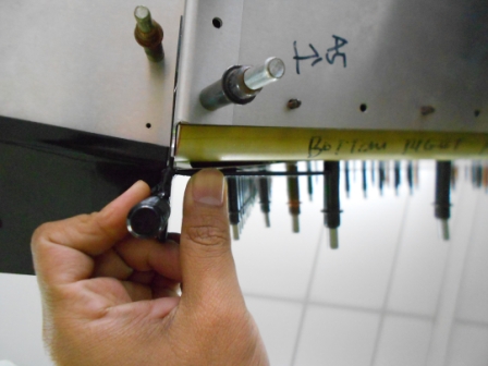
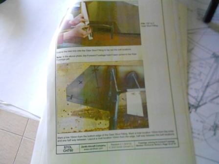
The Right Gear Strut Fitting is then pre installed on the Right Side Fuselage. A black line is then drawn from following the Side Channel line of rivets and the Bottom Fuselage line rivets. A 10 mm line from the bottom edge of the Gear Strut Fitting is then marked. A hole location 10 mm from the ends and one half between is also marked. A rivet location 10 mm from the edge which is half way between the bolt locations also have been layout.
- Hits: 177